
GUIDES
SYSTEM REVIEW - PRE-AUDIT GUIDE
AUDIT GUIDE
SENSOR INSTALLATION GUIDE - MODBUS
SENSOR INSTALLATION GUIDE - ANALOG INPUTS
CAL-EDGE-0 QUICK SETUP GUIDE
CAL-PM HMI GUIDE
MEASUREMENTS INSTRUMENTATION VERIFICATION & CALIBRATION GUIDE
TEMPLATES
SYSTEM REVIEW-PRE AUDIT FEASIBILITY STUDY TEMPLATE
EQUIPMENT SETUP CONNECTION TABLE
AUDIT FIELD INSTALLATION SETUP TEMPLATE
PERMANENT MONITORING FIELD INSTALLATION SETUP TEMPLATE
SENSOR INSTALLATION SETUP CHECKLIST
@ 2021 CALMS AIR inc.
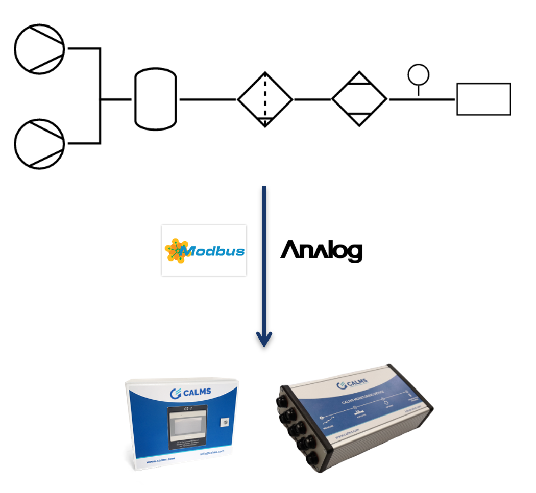
Connecting sensors, transmitters, master controllers and equipment controllers to CALMS device can be done with many different connection.
Standard supported
- Hardwire analog 4-20mA
- Modbus RTU – 485
- Modbus TCP via network switch
- ADS
- OPC …
Installing sensors network requires in-depth knowledge !
Please leave the installation to professional contractors.
Not following the specifications can result in incorrect communications and equipment damage!
CALMS devices that are supported in this manual are:
- CAL-PM-x - permanent monitoring and control device
- CAL-EDGE-0 - edge gateway
- CAL-EDGE-8 - audit temporary measurement device
On CALMS cloud application follow CALMS Setup documentation to create new system, start with general information about the system, where you must select and add edge device or more of them to the system.
Next Setup step is to create PI&D schematic of equipment and instrumentation used in the system. CALMS platform has integrated many standard sensors, compressor controllers and master controllers with predefined addresses and registers used in compressed air systems.
In case sensor is not available to select please contact CALMS support@calms.com with sensor model name, communication type and all comm settings together with sensor manual to verify settings.
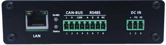
CAL-EDGE-0 gateway
CAL-EDGE-8 audit
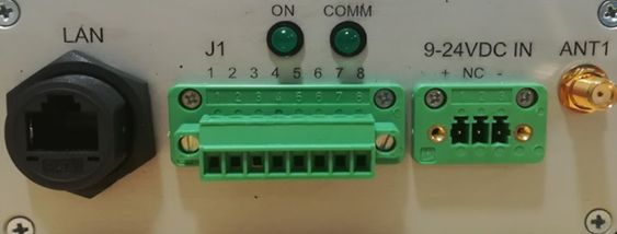
ON light must be on when device is connected to powersupply and complete software is running.
COMM light must blink when communication to the internet is working. If light is not blinking connect external internet by ethernet or mobile USB-LAN tethering to troubleshoot.
Check EDGE device manual for detail information about connections and technical details.
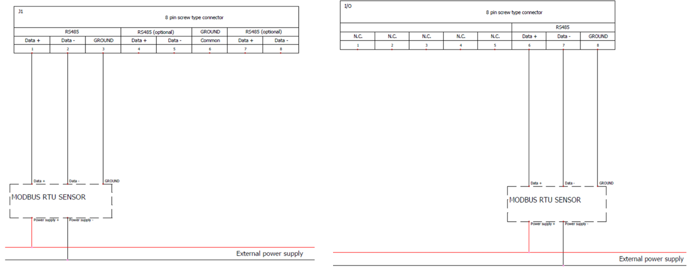
Modbus rtu – rs485 sensor connection
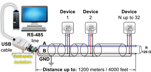
RS485 is a differential balanced line over twisted pair. It can span a relatively large distance up to 1200m | 4000 feet. However, you will have to be aware of the voltage drop: The power at the end of the line is not the same as at the beginning. It depends on the specific cable resistance and the power consumption of each sensor
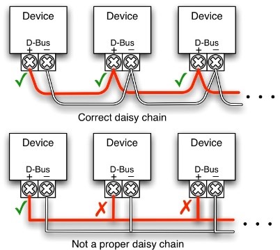
The wires should be connected in a point-to-point configuration, called a daisy chain.
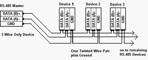
![]() Do not install a star or ring network. This may cause reflections of the signals.
Do not install a star or ring network. This may cause reflections of the signals.
- The main cable goes from the Master to all sensors. It contains three wires: the twisted pair wires (A = DATA- and B = DATA+) which carry the digital signal and the GND or “common” wire, which is absolutely essential for providing a proper reference to the Modbus transceivers.
- The main cable is shielded. Ideally, the shield is separated from the 0 Volt line, but it may be combined when you are absolutely sure that the shield is clean of voltage fluctuations.
When the line is longer then 10m use termination resistor. In case of an RS485 twisted pair cable this termination is typically between 120 and 130 Ω, between DATA- and DATA+.
TEST SENSOR CONNECTION WITH COMPUTER - LAPTOP
When all sensors are connected in daisy chain check that all device ID and comm parameters, wiring is correct with laptop with Modbus test software. You can use modbus scanner software like:
ModScan: https://www.win-tech.com/
CAS scanner modbus: http://freemodbus.com/download/
ModRSsim2: https://sourceforge.net/projects/modrssim2/
Simply modbus : https://www.simplymodbus.ca/RTUmaster.htmand USB to RS485 converter like DSD TECH SH-U11 USB to RS485.
MODBUS RTU – 485 Checklist
- [ ] Install sensor and connect power supply (check sensor manual), confirm that sensor is showing correct measurement on its local display (if provided)
- [ ] In case of multiple sensors, use RS485 daisy chain connection
- [ ] On each connected sensor in the daisy chain set the correct communication settings. Each sensor must have assigned unique Unit ID (MODBUS ID) and all sensors must have same communication parameters (Baud rate, Data bits, Stop bits, Parity)
- [ ] Prepare IQ (Instrumentation Qualification) table with signal names and all MODBUS communication settings (template can be found on www.docs.calms.com)
- [ ] Connect daisy chain to PC (use RS485 to USB converter) and test MODBUS readings of all sensors and confirm receiving proper values by filling IQ table
- [ ] If there are no readings or wrong values on PC MODBUS tester, double check communication parameters and wiring connection (try swapping A and B wires). In case readings are still not available contact sensor supplier.
- [ ] When all the readings on the PC are correct connect daisy chain to master CAL-EDGE device and follow the CALMS setup procedure with correct sensor setup – use IQ table.
- [ ] Verify all readings with CALMS and sensors and confirm receiving proper values by filling IQ table.
- [ ] If there are no charts and values in CALMS inspect page please send email to support@calms.com with system name and add support user the system. Attached photos of sensors setup page and connection connector with attached signal list and sensor manual.
![]()
If you request assistance from the CALMS support before completing the final checkbox step(marked with blue), we will charge you the hourly rate for support. Support costs are published in the CALMS price list.
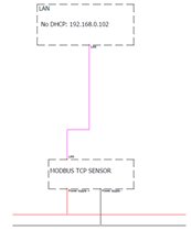
Modbus tcp ip ethernet sensor connection
CAL-EDGE has one standard RJ45 port used to implement TCP/IP connection. Supported protocols so far are: MODBUS TCP/IP, ADS and OPC UA. CAL-EDGE device has pre-configured fixed IP (192.168.0.102) in case there are not any DHCP servers in the network. If DHCP server is present in the network CAL-EDGE device will obtain IP from DHCP server.
![]() This port can also be used to connect device to the internet in case of 4G modem failure or low signal strength.
This port can also be used to connect device to the internet in case of 4G modem failure or low signal strength.
![]() For ethernet connection use sensor supplier cables or when creating your own cable make sure that shielded twisted pair (STP) is used. Max length for all Ethernet cables: 100 meters.
For ethernet connection use sensor supplier cables or when creating your own cable make sure that shielded twisted pair (STP) is used. Max length for all Ethernet cables: 100 meters.
For connecting multiple sensors to one CAL-EDGE use industrial routers.
MODBUS TCP/IP - Checklist
- [ ] Install sensor and connect power supply (check sensor manual), confirm that sensor is showing correct measurement on its local display (if provided)
- [ ] In case of multiple sensors, use industrial switches to establish a network of devices
- [ ] On each connected sensor in the network set the correct IP address. Each sensor must have assigned unique IP address
- [ ] Prepare IQ (Instrumentation Qualification) table with signal names and all MODBUS communication settings (template can be found on www.docs.calms.com)
- [ ] Connect PC to a network and test MODBUS readings of all sensors and confirm receiving proper values by filling IQ table
- [ ] If there are no readings or wrong values on PC MODBUS tester, double check communication settings and ethernet cables. In case readings are still not available contact sensor supplier.
- [ ] When all the readings on the PC are correct connect CAL-EDGE device to a network and follow the CALMS setup procedure with correct sensor setup – use IQ table.
- [ ] Verify all readings with CALMS and sensors and confirm receiving proper values by filling IQ table.
- [ ] If there are no charts and values in CALMS inspect page please send email to support@calms.com with system name and add support user the system. Attached photos of sensors setup page and connection connector with attached signal list and sensor manual.
If you request assistance from the CALMS before completing the final checkbox step(marked with blue), we will charge you the following costs.
Costs we incur in providing support to you.
Support costs are published in the applicable price list.
Compressed Air Instrumentation Verification & Calibration
Introduction
Compressed air is a critical utility in many industrial and commercial facilities. It is used to power tools, machinery, and other equipment. Compressed air audits can help identify inefficiencies and opportunities for improvement in compressed air systems. However, it is important to ensure that the measurement instrumentation used in compressed air audits is accurate and reliable.
The CALMS platform ensures precise measurements with a feature in the Setup that mandates verification of each sensor’s last calibration date. To manage the verification and certification of instrumentation, the Maintenance module keeps a log of all calibration records and sends alerts for timely verification, maintaining the system’s efficiency and compliance.
Measurement Instrumentation in Compressed Air for audits and permanent monitoring
Industrial measurement instruments used in compressed air audits, regular checks, verification, and calibration are key to maintaining accuracy and reliability. These instruments typically fall under Class B, as they’re not custody meters. Here’s a simplified guideline:
Instrument Type | Verification Frequency | Calibration Frequency |
Electric Current Transducers/Clamps | Annually | Every 2-3 years |
Powermeters | Annually | Every 2-3 years |
Flowmeters | Annually | Every 2-4 years |
Pressure Transmitters | Annually | Every 2-5 years |
Dew Point Meters | Annually | Every 2-5 years |
Temperature Transmitters | Annually | Every 2-3 years |
Air Quality Transmitters (Oil/Particles) | Annually | Every 2-4 years |
Vibration/Ultrasound Leak Detectors | Annually | 2-5 years or as recommended |
Always check manufacturer guidelines and specific industry standards for each type of instrument. The calibration frequency can vary based on usage intensity, environmental conditions, and the criticality of the measurements in your processes.
Instrumentation Verification
Measurement instrumentation verification is the process of ensuring that the measurement instrumentation used in compressed air audits is accurate and reliable. This process involves comparing measurements with similar device and comparing values which should be in the range of +-5% or as defined by standards. This procedure is low-cost and can normally be done in the field (on site)
Instrumentation Calibration
Calibration is the process of comparing the measurement instrumentation to a known standard, which is a traceable reference meter with much higher accuracy and measure deviation. This standard can be a physical device, such as a pressure gauge, or a mathematical model. The measurement instrumentation is then adjusted until it matches the standard. This procedure is normally done in the Lab based on standard conditions (like ISO17025) or in the field with the maximum permissible error of 3x or 5x.
Testing
Testing is the process of using measurement instrumentation to measure a known quantity. This quantity can be a flow rate, pressure, or temperature. The measurement instrumentation is then compared to the known quantity to ensure that it is measuring correctly.
Benefits of Measurement Instrumentation Verification
Measurement instrumentation verification has several benefits, including:
● Improved accuracy of compressed air audits
● Reduced risk of errors in compressed air audits
● Increased confidence in the results of compressed air audits
● Improved efficiency of compressed air systems
● Reduced energy costs
Conclusion
Measurement instrumentation verification is an important part of compressed air audits and permanent monitoring. By ensuring that the measurement instrumentation is accurate and reliable, compressed air audits can provide valuable insights into the efficiency of compressed air systems.
Routine checking sensors on site
This is where a portable checking device is taken to the sensor measuring point in the process and, in parallel to the live online sensor, corroborates the accuracy of the installed sensor. To be reliable, it is recommended that a minimum of three measuring points are checked across the likely working range of the sensor in the process. This is normally defined as an as found check; not a calibration or recalibration. This is a quick operation that does not disrupt the process; however, it will not be as accurate as the second method, described below.
Calibrating sensors in an approved laboratory
This is where the installed sensor is taken from the process into a stable workshop and, using a calibration reference with an inaccuracy factor lower than the sensor being checked, is calibrated across multiple points, using a controlled process and a trained operator.
This is normally undertaken with an as found check and then (if required) an as left (adjusted) calibration. This takes longer and requires the use of a spare calibrated replacement sensor, to ensure the continuation of the process.
Standards
ISO 8573: Specifies the quality of compressed air, detailing requirements for contaminants like particles, water, and oil. Essential for air quality transmitters and ensuring compliance with purity specifications.
ISO 1217: Focuses on performance testing for displacement compressors, including methods for measuring flow rates. Critical for calibrating flowmeters.
ISO/IEC 17025: A general standard for testing and calibration laboratories, emphasizing competence, consistent operations, and reliable output.
IEC 61557: Pertains to electrical safety in low voltage distribution systems, relevant for calibrating electric current transducers and power meters.
ASME PTC 19.3: Relates to temperature measurement, applicable for calibrating temperature transmitters.
ISO 6789: Concerns the calibration of hand-operated torque tools, relevant for various equipment in industrial settings.
IEC 60770-1: Specifies performance requirements for transmitters in industrial-process control systems, including accuracy, environmental conditions, and testing.