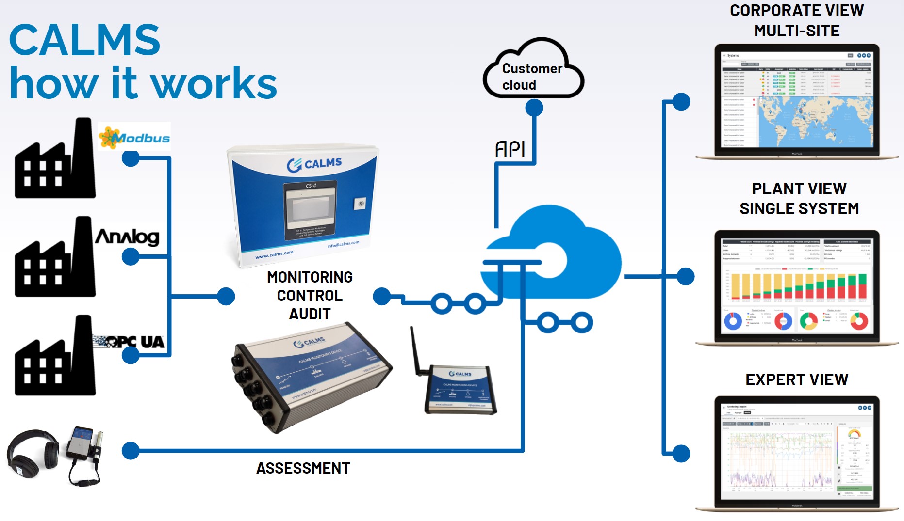
CALMS schematic
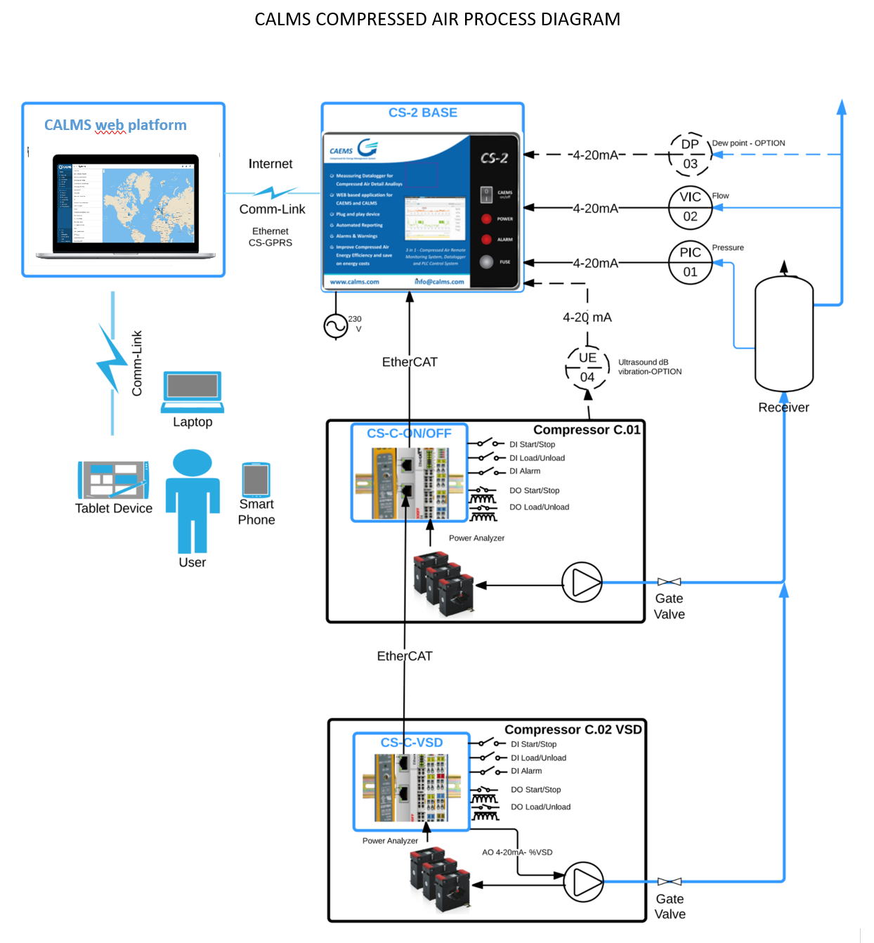
CALMS process diagram
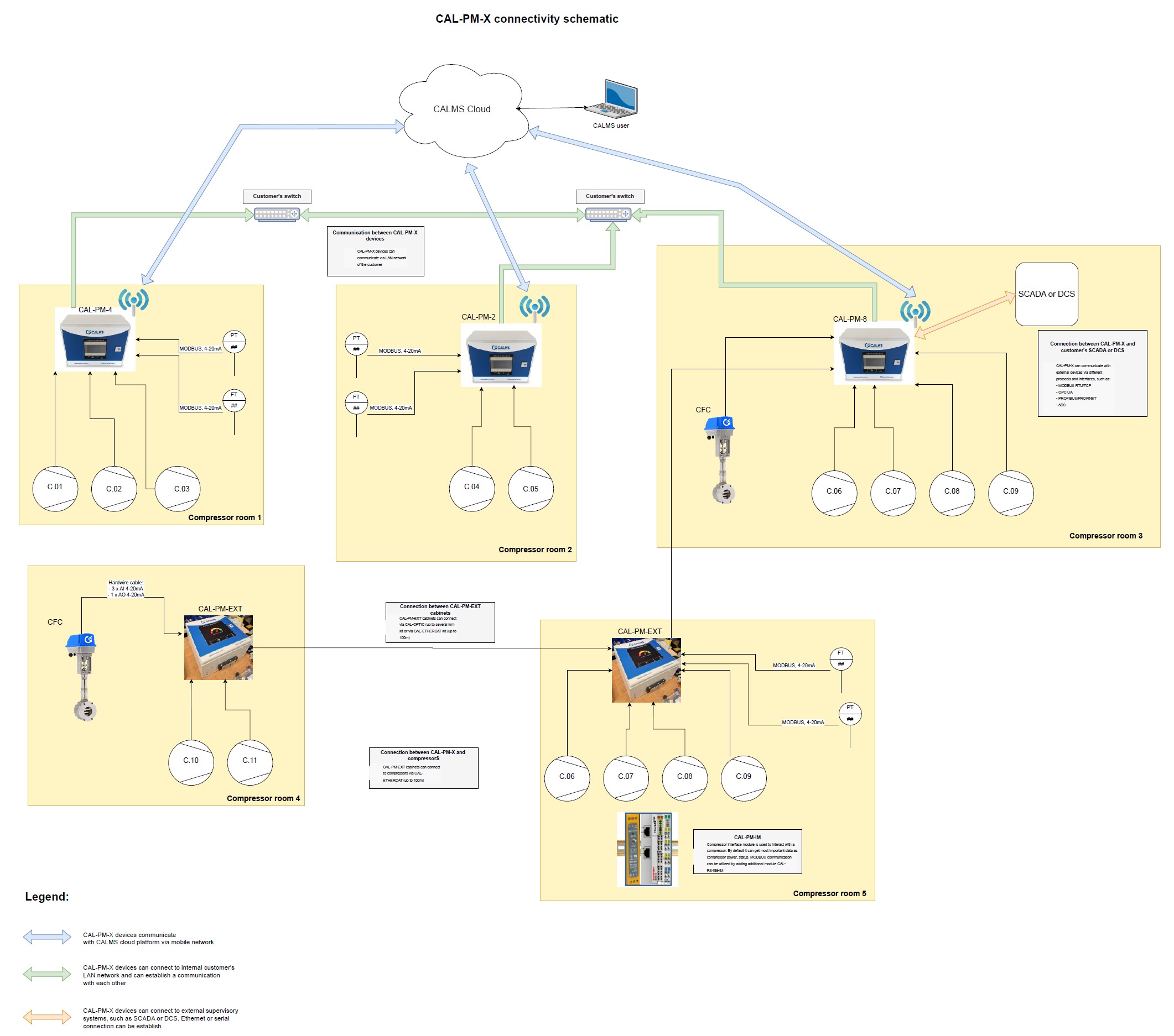
CALMS connectivity schematic
CALMS system is designed to facilitate efficient communication and integration across multiple locations, leveraging various sensors, control equipment, and advanced communication protocols. Below is an overview of how CALMS systems can connect and communicate in distributed environments.
System Connectivity Overview
- Communication Between CALMS Systems:
- CALMS devices, such as CAL-PM-X units, can communicate across multiple locations through the customer’s Ethernet LAN or via dedicated optical fiber connections using the CAL-OPTIC kit (up to several kilometers) or the CAL-ETHERCAT kit (up to 100 meters).
- This enables real-time data exchange between systems for optimal performance and centralized control.
- Sensor and Control Equipment Integration:
- CALMS supports integration with a variety of sensors (e.g., pressure, flow, and temperature) and control equipment. These devices communicate using:
- MODBUS (RTU/TCP)
- Analog Signals (4-20mA, AI/AO)
- Other Protocols (e.g., OPC UA, PROFIBUS/PROFINET, ADS).
- Each compressor room or control point can host its own CALMS system (e.g., CAL-PM-2, CAL-PM-4, CAL-PM-8), connected to individual compressors or subsystems.
- CALMS supports integration with a variety of sensors (e.g., pressure, flow, and temperature) and control equipment. These devices communicate using:
Connectivity Options
- Customer Ethernet LAN:
- CALMS devices can integrate into the customer’s existing LAN infrastructure, ensuring seamless communication between units.
- Data and control signals are transmitted securely over the internal network, providing a cost-effective and reliable solution.
- Dedicated Optical Connections:
- For long-range connectivity, CALMS systems can use optical fiber via the CAL-OPTIC kit, capable of spanning several kilometers while maintaining high data transmission rates.
- External Supervisory Systems:
- CALMS systems can interface with external SCADA, DCS, or similar platforms for supervisory control and data acquisition.
- Supported connections include:
- Ethernet
- Serial Interfaces
- Protocols like MODBUS RTU/TCP, OPC UA, and PROFIBUS ensure compatibility with a wide range of external systems.
- Cloud Connectivity:
- CALMS devices can communicate with the CALMS Cloud platform via a mobile network or Ethernet LAN, enabling remote monitoring, analytics, and system optimization.
Application Example
- Compressor Rooms Across Locations:
CALMS units (e.g., CAL-PM-X) are installed in multiple compressor rooms distributed across a site or even geographically separated facilities. These units are connected via a combination of Ethernet LAN or optical fiber and communicate in real-time with the customer’s SCADA or directly with the CALMS Cloud for centralized management.
Key Advantages
- Scalability: The system is designed to accommodate operations ranging from a single site to large-scale distributed networks.
- Flexibility: Offers multiple connectivity options to suit diverse infrastructure setups.
- Interoperability: Seamless integration with third-party supervisory systems ensures efficient coordination across all levels of operation.
- Reliability: Dedicated options like CAL-OPTIC ensure high-speed and secure communication over long distances.
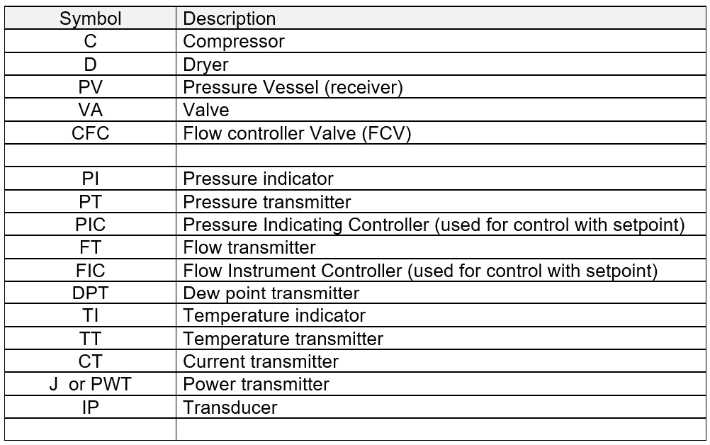
Process Instrumentation Diagram (P&ID) Symbols
A Process Instrumentation Diagram (P&ID) is a detailed diagram in the process industry which shows the piping and process equipment together with the instrumentation and control devices. Here’s a breakdown of its key features:
- Overview: P&IDs represent the physical arrangement of equipment and the piping required to connect each piece of equipment. They serve as a roadmap for the design and operation of a process facility.
- Components: These diagrams typically include:
- Process equipment like pumps, compressors, heat exchangers, tanks.
- Piping systems, including pipe sizes, pipe material, and flow directions.
- Instrumentation and control devices, like sensors (pressure, temperature, flow, etc.), controllers, and their interconnections.
- Operational details, such as process conditions (pressure, temperature), fluid properties, and flow rates.
- Symbols and Notations: P&IDs use standardized symbols and notations to represent different components and control strategies. This includes valves, instrument symbols (like PT, TT), and line symbols.
- Purpose:
- Design and Engineering: P&IDs are crucial in the design phase, helping to lay out the process flow and integrate equipment and control.
- Operation and Maintenance: They are used to understand the process flow and for troubleshooting, maintenance, and modification of the process.
- Safety and Compliance: P&IDs are essential for safety analysis and compliance with regulatory standards.
- Development and Usage: P&IDs are developed during the design phase of a project and are updated throughout the lifecycle of a facility to reflect any modifications.
CALMS is using standard symbols for compressed air and other utilities.
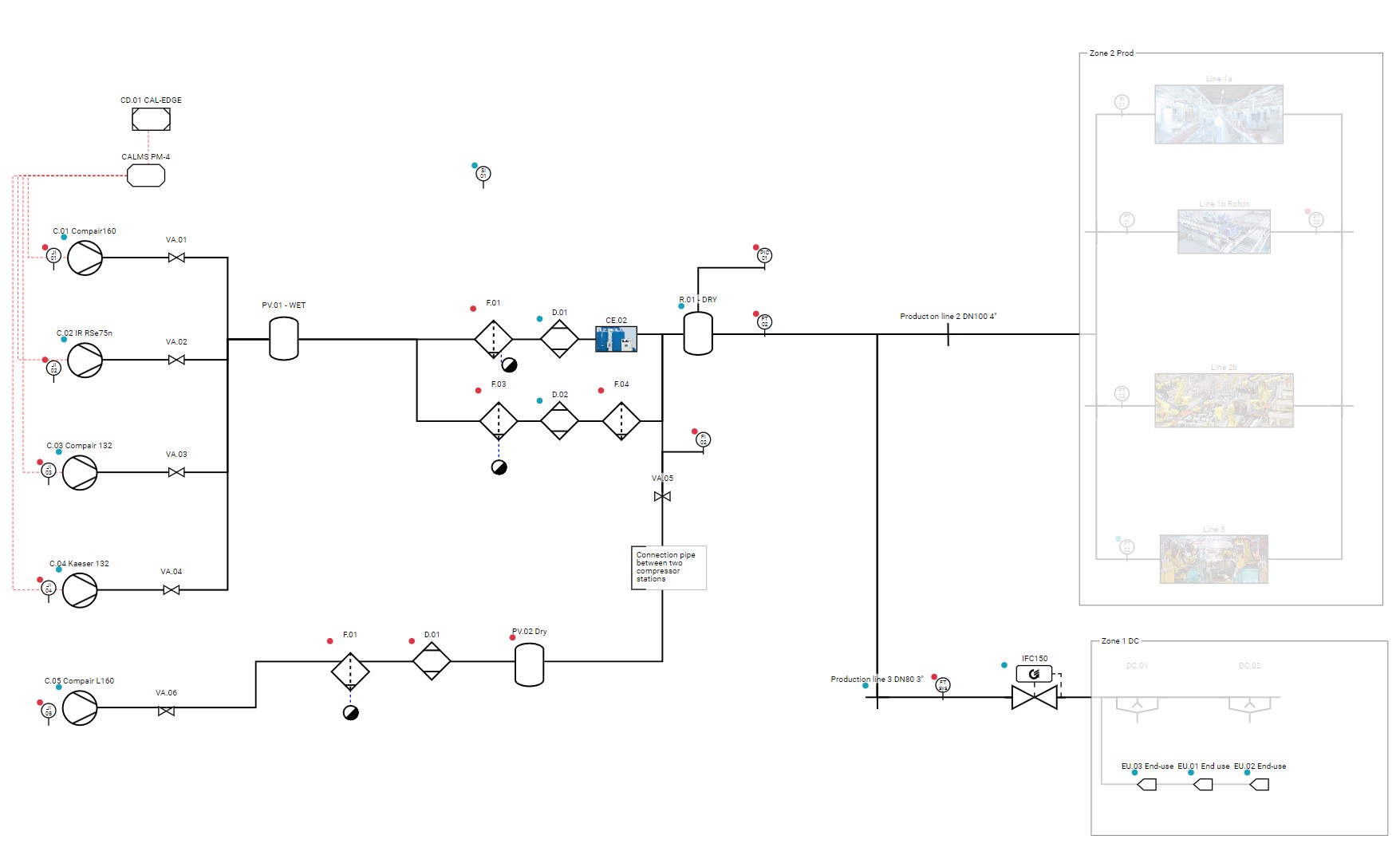
Sample CALMS P&ID
Standard symbols for instrumentation used in CALMS
- Flow:
- Instrument: FI (Flow)
- Transmitter: FT (Flow Transmitter)
- Control: FIC (Flow Indicating Controller)
- Pressure:
- Instrument: PI (Pressure)
- Transmitter: PT (Pressure Transmitter)
- Control: PIC (Pressure Indicating Controller)
- Temperature:
- Instrument: TI (Temperature)
- Transmitter: TT (Temperature Transmitter)
- Control: TIC (Temperature Indicating Controller)
- Dewpoint :
- Instrument: DPI (Dewpoint)
- Transmitter: DPT (Dewpoint Transmitter)
- Control: DPIC (Dewpoint Indicating Controller)
- Power :
- Instrument: J Ior PWRI (Power)
- Transmitter: JT or PWRT (Power Transmitter)
- Control: JIC or PWRIC (Power Indicating Controller)
- Energy :
- Instrument: EI (Energy)
- Transmitter: ET (Energy Transmitter)
- Control: EIC or EIC (Energy Indicating Controller)
- Electric Current
- Transmitter: CT (Current Transmitter)
- Electric Current
- Transmitter: CT (Current Transmitter)
- Electric Current
- Transmitter: CT (Current Transmitter)
- Voltage
- Length
- Time
- Digital state
- Specific power
- Vibration
- Ultrasound
- Mass
- Velocity
- Volume
- Count
- Rate
- Ratio
- Mass flow
Table P&ID symbols in CALMS