CALMS SCHEMATICS
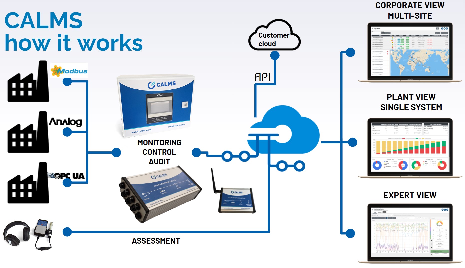
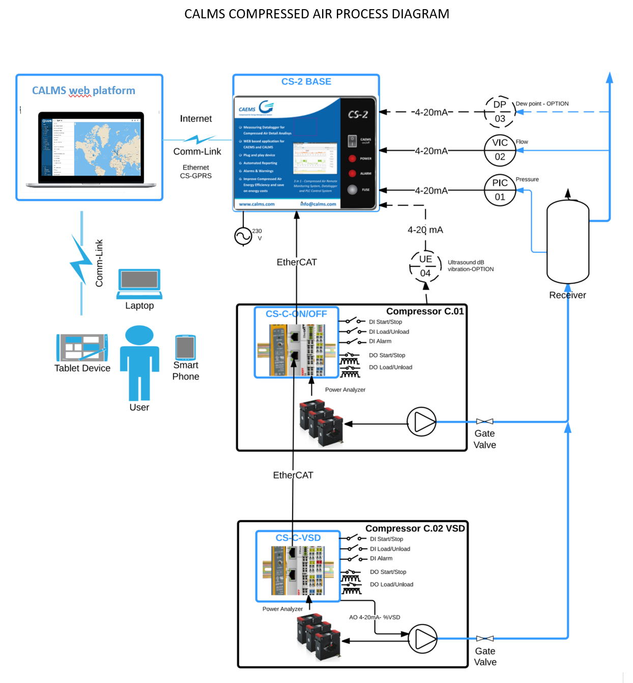
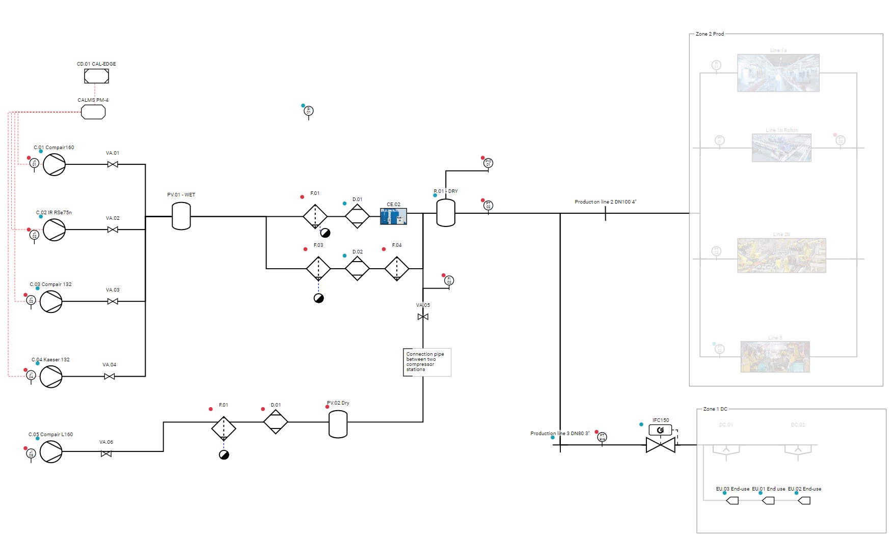
CALMS PROCESS DIAGRAM
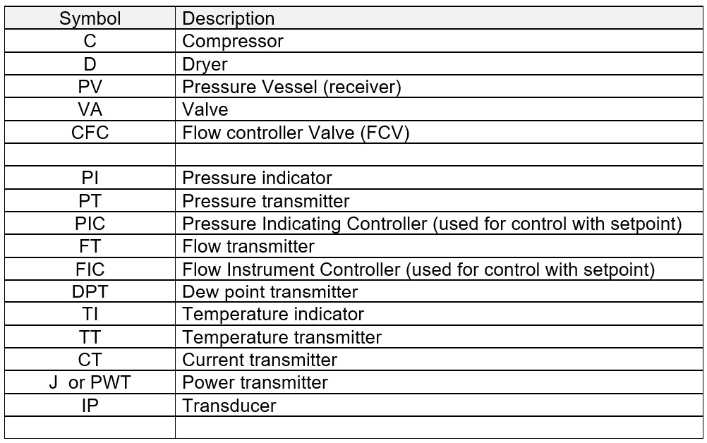
Process Instrumentation Diagram (P&ID) Symbols
A Process Instrumentation Diagram (P&ID) is a detailed diagram in the process industry which shows the piping and process equipment together with the instrumentation and control devices. Here’s a breakdown of its key features:
- Overview: P&IDs represent the physical arrangement of equipment and the piping required to connect each piece of equipment. They serve as a roadmap for the design and operation of a process facility.
- Components: These diagrams typically include:
- Process equipment like pumps, compressors, heat exchangers, tanks.
- Piping systems, including pipe sizes, pipe material, and flow directions.
- Instrumentation and control devices, like sensors (pressure, temperature, flow, etc.), controllers, and their interconnections.
- Operational details, such as process conditions (pressure, temperature), fluid properties, and flow rates.
- Symbols and Notations: P&IDs use standardized symbols and notations to represent different components and control strategies. This includes valves, instrument symbols (like PT, TT), and line symbols.
- Purpose:
- Design and Engineering: P&IDs are crucial in the design phase, helping to lay out the process flow and integrate equipment and control.
- Operation and Maintenance: They are used to understand the process flow and for troubleshooting, maintenance, and modification of the process.
- Safety and Compliance: P&IDs are essential for safety analysis and compliance with regulatory standards.
- Development and Usage: P&IDs are developed during the design phase of a project and are updated throughout the lifecycle of a facility to reflect any modifications.
CALMS is using standard symbols for compressed air and other utilities.
Sample CALMS P&ID:
Standard symbols for instrumentation used in CALMS
- Flow:
- Instrument: FI (Flow)
- Transmitter: FT (Flow Transmitter)
- Control: FIC (Flow Indicating Controller)
- Pressure:
- Instrument: PI (Pressure)
- Transmitter: PT (Pressure Transmitter)
- Control: PIC (Pressure Indicating Controller)
- Temperature:
- Instrument: TI (Temperature)
- Transmitter: TT (Temperature Transmitter)
- Control: TIC (Temperature Indicating Controller)
- Dewpoint :
- Instrument: DPI (Dewpoint)
- Transmitter: DPT (Dewpoint Transmitter)
- Control: DPIC (Dewpoint Indicating Controller)
- Power :
- Instrument: J Ior PWRI (Power)
- Transmitter: JT or PWRT (Power Transmitter)
- Control: JIC or PWRIC (Power Indicating Controller)
- Energy :
- Instrument: EI (Energy)
- Transmitter: ET (Energy Transmitter)
- Control: EIC or EIC (Energy Indicating Controller)
- Electric Current
- Transmitter: CT (Current Transmitter)
- Electric Current
- Transmitter: CT (Current Transmitter)
- Electric Current
- Transmitter: CT (Current Transmitter)
- Voltage
- Length
- Time
- Digital state
- Specific power
- Vibration
- Ultrasound
- Mass
- Velocity
- Volume
- Count
- Rate
- Ratio
- Mass flow
Table P&ID symbols in CALMS