Setup is the most important part for defining each system and must be filled completely to get the fully functional system.
The Setup menus are structured in 5 consequential steps : General, Equipment, Target, Channels and Permissions. System manager must followed all menus step-by-step from left to the right.

CALMS is using dots (blue and red) to indicate that some data are not confirmed or missing. Blue dot means system data are not confirmed, red dot means that essential data is missing.
General
General page is where you start with each system setup and where you have to set all basic system information.
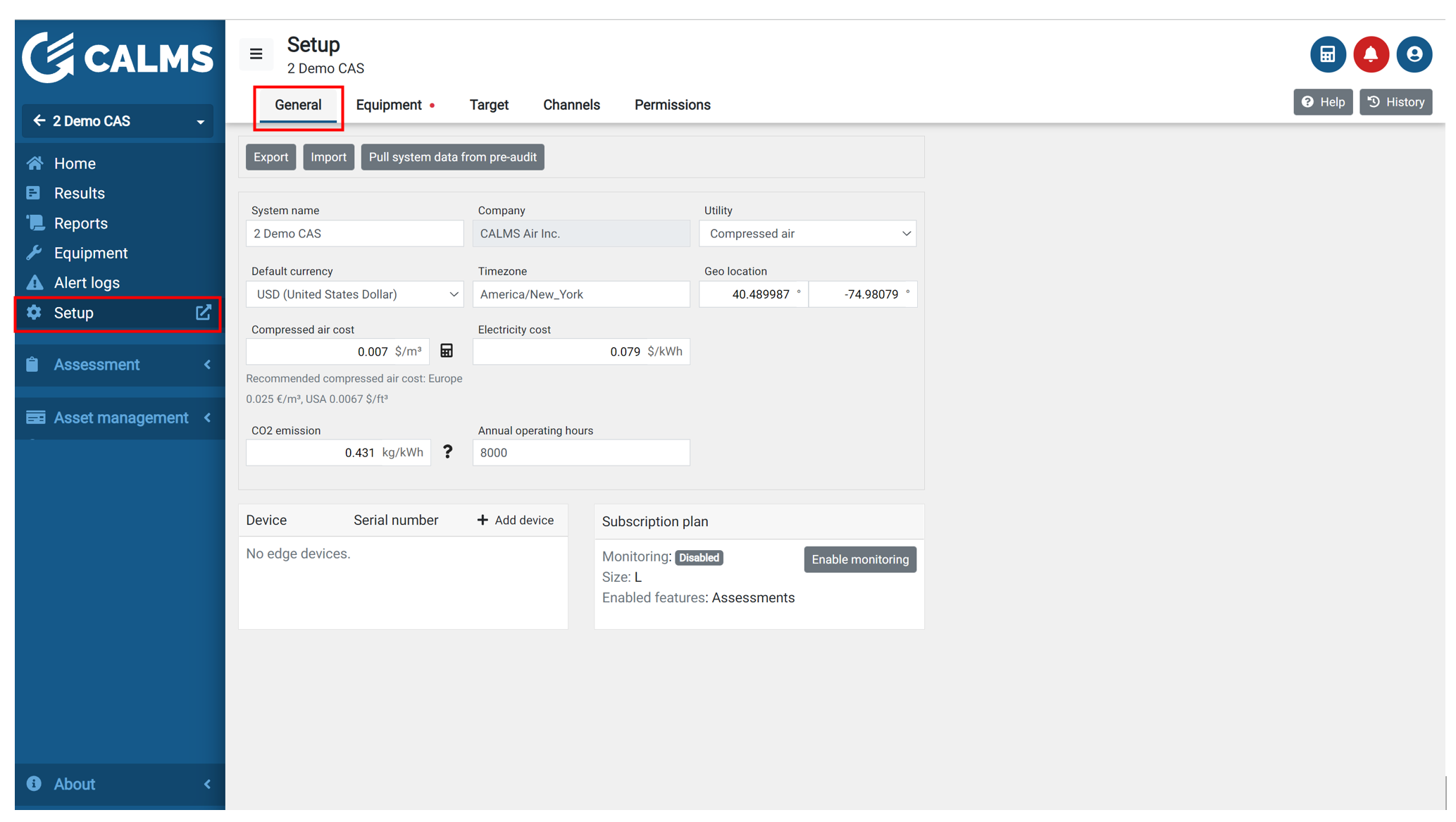
You can add or change the system name, utility type, default currency, time zone, geo location, electricity cost, CO2, operation hours, device attached to the system and subscription type…
To start with Setup you can IMPORT data from previous system or you can Pull data from pre-audit in case you start with pre-audit first. You can also Export system setup data in case you want to use it in different system or as local backup.
NOTE: Is it important to fill in all data, because some auto calculations are based on these inputs.
To change units you have to go to personal settings.
NOTE: If you want to change the company, you must go to the Partner Panel and find a system whose name you want to change in the System section.
NOTE: Geo location will entered automatically if you will add system to the company with correct address. Otherwise use Google Maps for geo location. Type address and in your URL you will find your longitude and latitude values.
When you finish you have to press SAVE button in right corner.
CO2 emission
Decarbonizing electricity generation will be critical if we are to achieve cuts in global greenhouse gas emissions.
The CO2 from electricity generation emissions is a country based value that is changing over time. Please check which value is relevant for your country.
Some useful links:
- Electricity map - carbon intensty per county
- Greenhouse gas emission intensity of electricity generation in EU
- Climate change mitigation policies by country
Devices in the system
To use monitoring, one or more devices must be added to system. “Add device” button will open pop-up where you can select a device that you have access to. If your device is not on the list please contact support@calms.com.

If the device is already used in a system, there are two options:
- the device can be transferred from original system to new system with Transfer button (recommended),
- the device can be used in multiple systems at the same time with button Use in multiple systems.
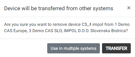
NOTE: When you transfer device to new system, old system will not measure data anymore. But data and channels will still be stored in original system.
The config of the device (what and how to measure) is automatically generated from the equipment setup. This is why it is important to add your device into correct system.
Start / pause device
Under Setup/general there is play/pause button to enable and disable device remotely.

- Pause device remote monitoring - disable device
- Start remote monitoring - enable device
- Device Setup and device dashboard, also delete device from the system
- No permission for device management
Even if device is disabled it will still log data in internal memory unless it is disconnected from power supply.
Subscription plan
This manual provides guidelines for the subscription plan in the CALMS platform. Subscription Plan provides various options based on the number of measured channels that are stored in the system. The subscription plan validity is one year and will be automatically updated until marked as DISABLED (gray or red). System Manager and System Admin have different privileges for selecting a subscription plan. Basic Plan is available to all and activates all features except permanent monitoring.
System manager must order and purchase enough subscription plans in advance as a credits that he can use to create or update systems valid subscription. Based on valid price book volume discounts are available.
System Manager can create a new system and select a subscription plan based on customer order and confirm valid date. Only System Admin can select F - Free of charge demo system and XXL - special large system.
For each system subscription plan must be selected in Setup / General page with button Subscribe:

If a subscription is active system manager can still change the subscription plan and he can also activate audit (temporary measurements with unlimited channels) for one month

Subscription Plan Selection
The only criterion for selecting a system subscription model is the number of measured channels that are stored in the system (measurements). When a new system is created, the System Manager must select a subscription plan. The available subscription plans are:
- B - Basic Plan
- S - Small Plan
- M - Medium Plan
- L - Large Plan
- XL - Extra Large Plan
- F - Free Demo System (System Admin Only)
- XXL - Special Large System (System Admin Only)
Just for orientation, XS and S is normally a small system with up to 2 compressors, M is a medium system with up to 4 compressors, L is a large system with up to 8 compressors and XL is a system with more than 8 compressors.
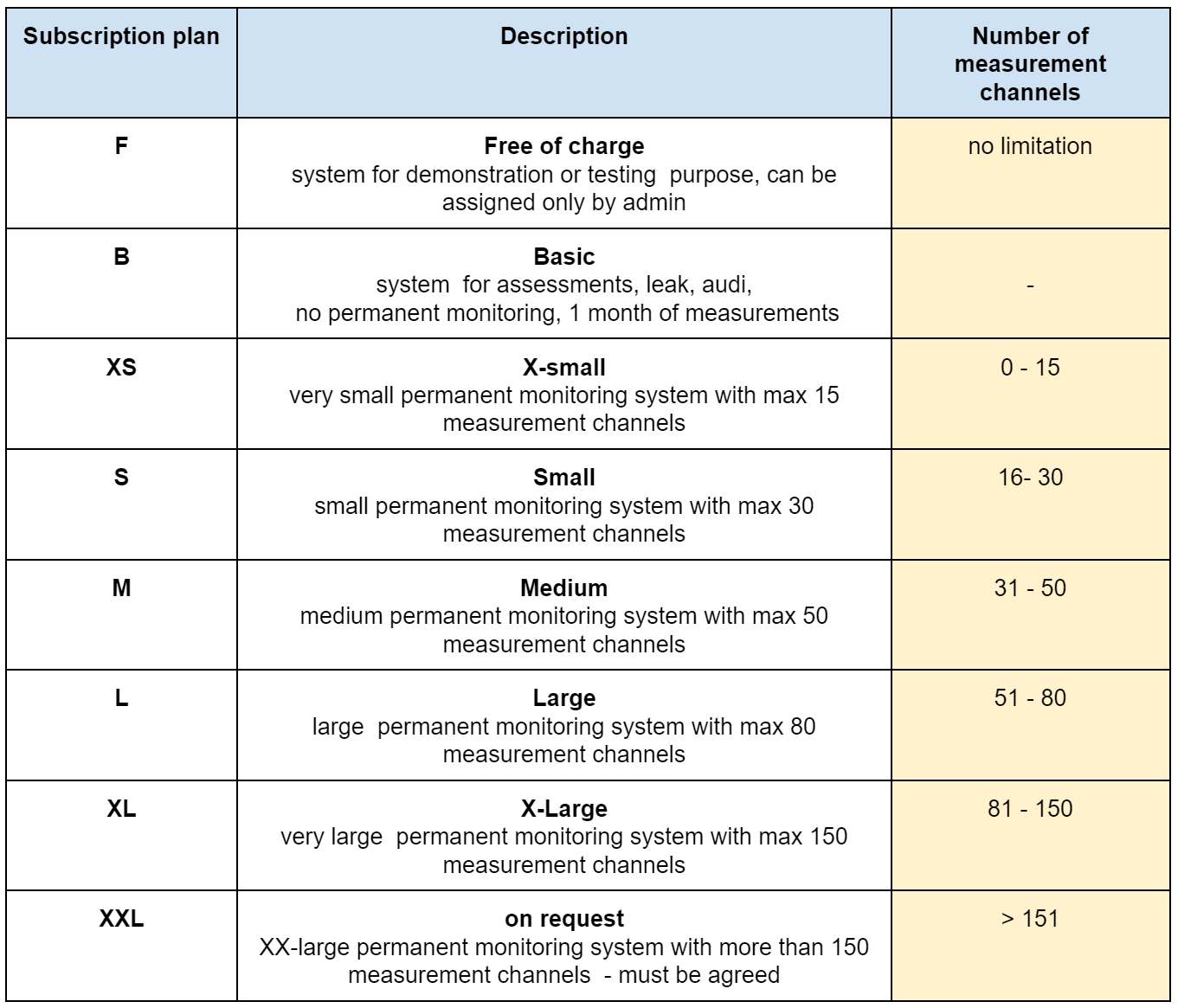
The valid actual subscription plan is in CALMS Price book. And can be changed without notice.
With button Subscribe manager can select all available plans based on the purchase order. Manager can select only plans that have been purchased and have blue number of available credits. Also the number of measurement channels is the limitation for selection -red alert notification under unavailable plans.
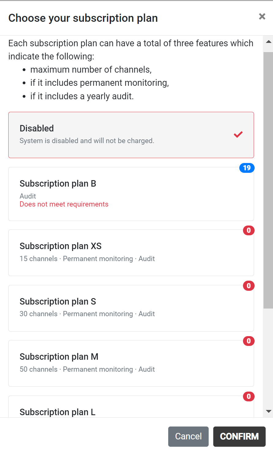
Confirm the subscription plan duration - up to 10 years if you have purchased enough credits.
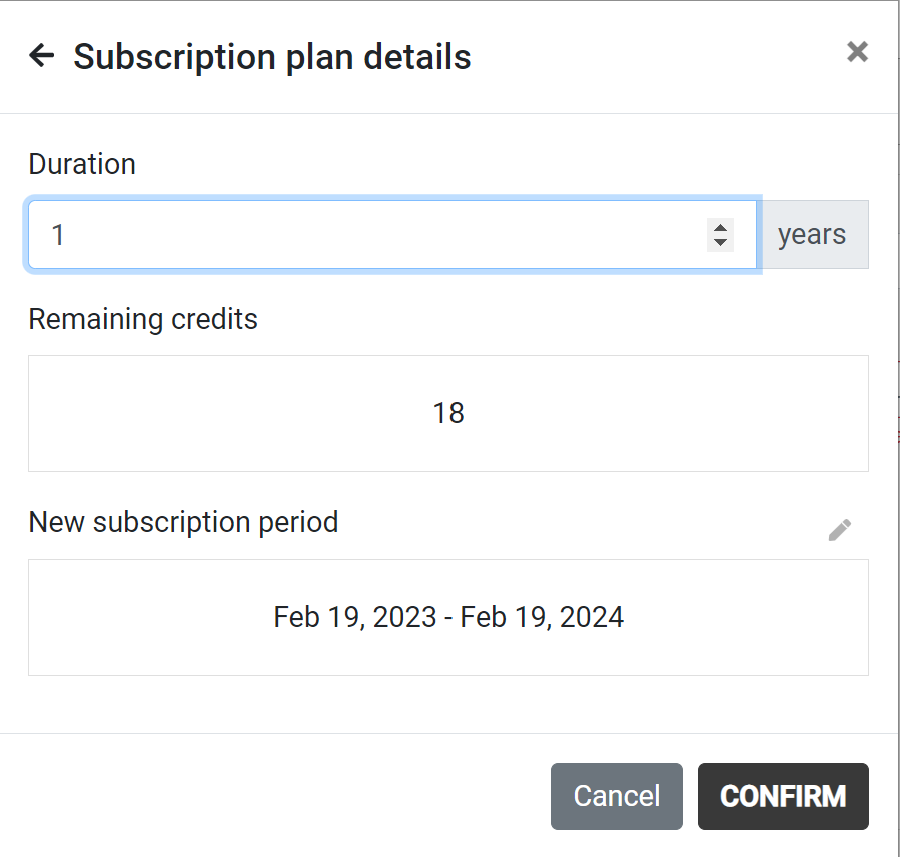
Subscription Plan Details
The Basic Plan activates all features except permanent monitoring. Also, audits with unlimited channels can be used for one month of measurement. If the user wants to have measurements for more than one month, they must select a subscription plan for permanent monitoring based on size or another Basic plan. The Basic plan will notify the user 14 days upfront to upgrade or renew the subscription plan with the one for permanent monitoring or another Basic or disable the device after one month of measurement.
Subscription Plan Validity
Subscription for the system is valid for one year and will be automatically updated until marked as DISABLED. When Disabled, all selections (menus) will be locked and hidden, except Setup.
Activation of Monitoring in Basic plan
If the Basic plan is selected, monitoring must be enabled with adding new devices and activating them by pressing the button Change monitoring or Activate temporary monitoring. For Basic plan with temporary monitoring, when the date is overdue, a pop-up window will display to Change the plan, where the user can change to a permanent plan or disable the system.
Disabled / locked systems
The system is locked in the following cases:
- You have manually disabled the system (i.e. you do not wish to renew your subscription)
- You have too many channels for your subscription.
- Your subscription has expired.
What do we do when the system is disabled / locked?
- Before system will get locked , system manager will receive alart notification 14 days before expiring date
- It is marked red in the list of your systems (or grey if you manually disable it).
- All pages of the system are locked (including the dashboard) except the setup, which remains completely enabled.
Billing page
System manager has an overview of all available (purchased) subscription plans in Manager menu under the billing page.
There is also a link under manager menu/system to have list of all created systems and planed and valid dates.

Equipment
Equipment page is the most important page where Piping and Instrumentation diagram (PID) of compressed air system with equipment elements and instrumentation can be created. This will build model of the system, equipment list and channel list automatically.
Standard CALMS edge device can connect via many different communication protocols such as analog or digital inputs, Modbus and ADS. To configure these connections at your device, you can use the CALMS configuration database that contains most common instruments available on the market.
If you are using generic standard analog 4-20mA instrument you can add this from standard analog list.
In case you have an instrument that is not in the database and is using Modbus or any other protocol please contact support@calms.com to add new instruments. Please attach data sheet and Modbus settings.
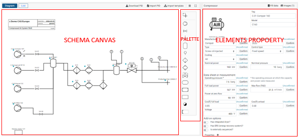
Diagram
Adding elements
To add an element to your diagram:
- in the palette on the right side of the canvas, select an element with single mouse click,
- place it by second click on the canvas position where you want this element to be.
Elements in palette are symbols for equipment that you can use for schematic diagram. Elements include symbol for compressor, valve, end user point-junction, receiver, instrument, filter, dryer, pressure-flow controller, monitoring device, control device, custom, drain and text box.
Deleting and connecting elements
When you click on an element, it highlights and opens a context menu, where you can:
- connect this element some other element by click on the tool icon in context menu and then clicking element you want to connect to (will change to green).
- delete the selected element with X.

Saving, loading and exporting
This diagram editor supports exporting in .pid file format. You can save the file to your computer and load it as some later time to make new edits.
It also supports export in SVG image format that can be previewed in any image viewing software or edited in any vector editing software.
These actions can be performed with buttons on the top right of the editor.
NOTE: It is very important that correct PI&D schematic is correct and completely filled in with all equipment data from data sheets and name plates. All essential data must be also confirmed, blue dot is showing not confirmed data and red dot is showing missing essential data.
Properties
When you select an element from the canvas its properties panel opens on right of the canvas. Different elements have different properties you can edit. You can also upload images of the equipment.
Sensors - data collection
Monitoring data collection is configured using instruments or sensors. When an instrument (use sensor icon) is added to the diagram, you can select the appropriate configuration from the CALMS database. This database is filtered by the capabilities of your device and selected measurement quantities (i.e. power, flow, pressure, power…other).
First step is to select device where you will connect sensor (only if you have multiple devices) - if only one device is in the system - this window will not appear.

And finally you have to select sensor by name, quantity or manufacturer from sensor database. List of sensors depends from the device you have, the communication links the device can handle and selected equipment. There are also generic standard analog sensors that you can select and setup. If you select on P&ID compressors only compressor controllers or master controllers will be available to select.
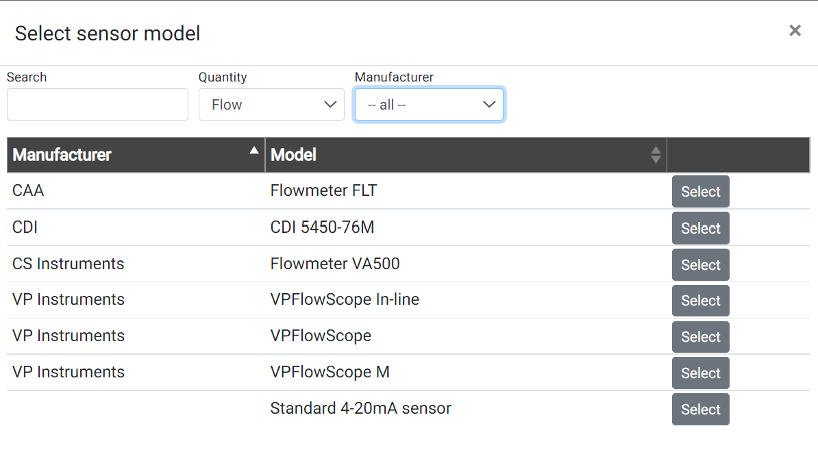
If sensor is not listed and it is not generic type, please send inquiry for adding new sensor to [support@calms.com]( “Support email”) . Please add sensor exact model and manufacturer, connection protocol, manual with addresses and special instructions if needed (like which parameters can be changed during setup)
Most configurations have at least some required fields that have to be filled for the successful connection, such as label of analog port or Modbus unit id. These fields can be found on the right of the canvas.
You can also attach instruments to any other equipment in the system using “Connect sensor” button.
When configuring your instruments, CALMS will create channels where collected data will be written to. When applicable, CALMS will ask you if you want to write data into existing channels.
Each channel has additional configuration settings, most of which are described below.
Please use standard SI TAG designation, like PI (Pressure Indicatior), PT (Pressure Transmitter), PIC (Pressure Indicating Control). https://docs.calms.com/technical-references/ca_process_diagram/#standard-symbols-for-instrumentation-used-in-calms
Sensor have element properties that must be filled on the right side. Standard sensor properties are divided in two sections:
- Instrument details with tag, image, model
- communication configuration if needed for modbus and other protocols
- measurement channel configuration
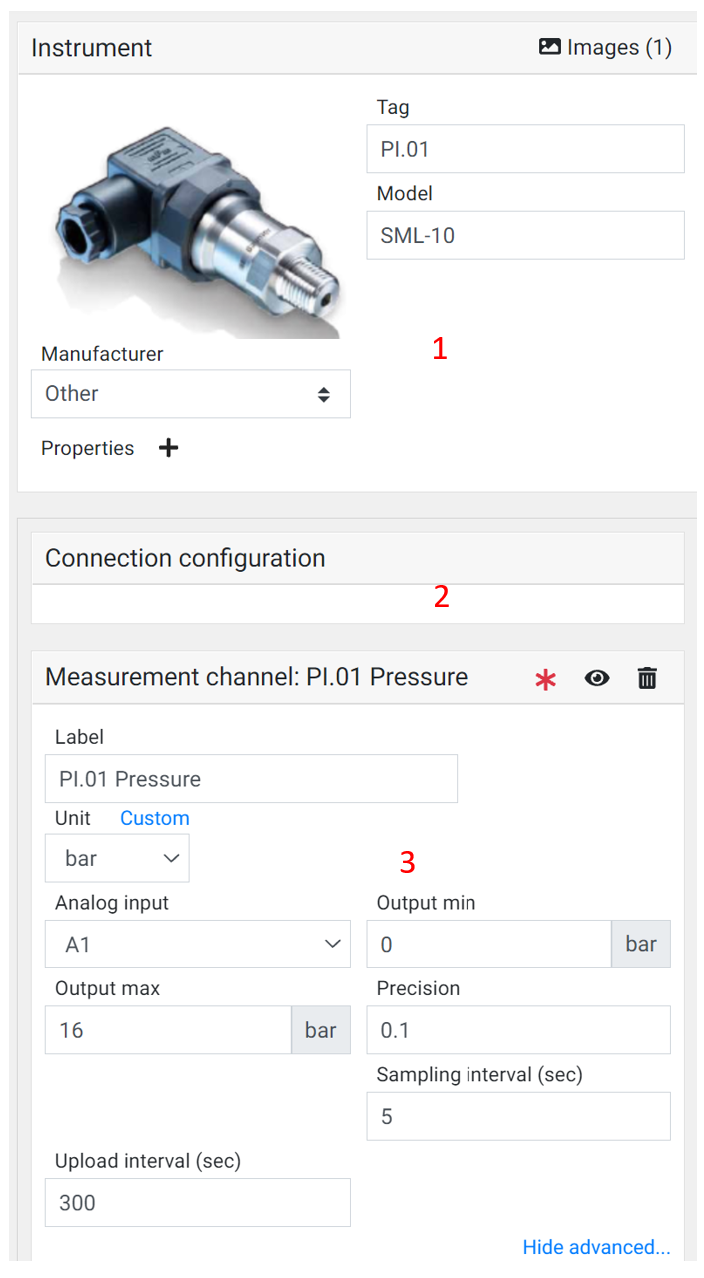
Under measurement channel configuration user must define channel label (default name is TAG + quantity), select input on device (analog or address or IP), signal range (min-max) and standard setting:
Sampling interval
Time rate at which device will collect measurements from instrument or controller. Default value is 5 sec, minimal value is 1 sec.
Upload interval
Time rate at which device will send collected data to the server. Default (and recommended) value is 5 min. Higher rates may incur additional data transfer fees.
Precision
The smallest change in signal measurements that will be measured and collected.
For example, if precision is set to 0.02 kW, and the values changes from 2.74 kW to 2.75 kW, the change will not be collected, and the value on the plot will show 2.74 kW. This greatly reduces amount of data transferred, allowing higher sampling intervals with same transfer rate.
If precision is set to -1 all values will be measured.
Zero filter
Any value with absolute value less than zero filter will be mapped into 0. This is useful when, for example, flow instrument equipment has measurement error and values fluctuate around 0, even producing negative values.
Analog 4-20mA settings
Output range min and max value. Select device input (usually A1..A8)
Modbus TCP IP Ethernet settings
Instruments with Modbus RTU communication have all default sensor parameters (registers, addresses, ..) already programmed in CALMS database, so you only select instrument by model and set necessary parameter: IP instrument address.
Modbus RTU 485 settings
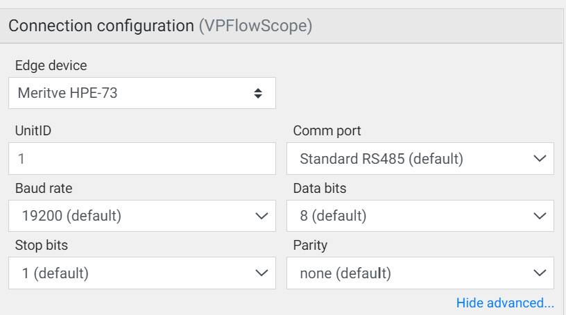
Instruments with Modbus communication have all default sensor parameters (registers, addresses, communication baud, parity..) already programmed in CALMS database, so you only select instrument by model and set necessary parameters which can be actually changed on instrument like :Modbus Unit ID, Baud rate, data bits, stop bits and parity (but they are already set as instrument default values).
Compressors - data collection
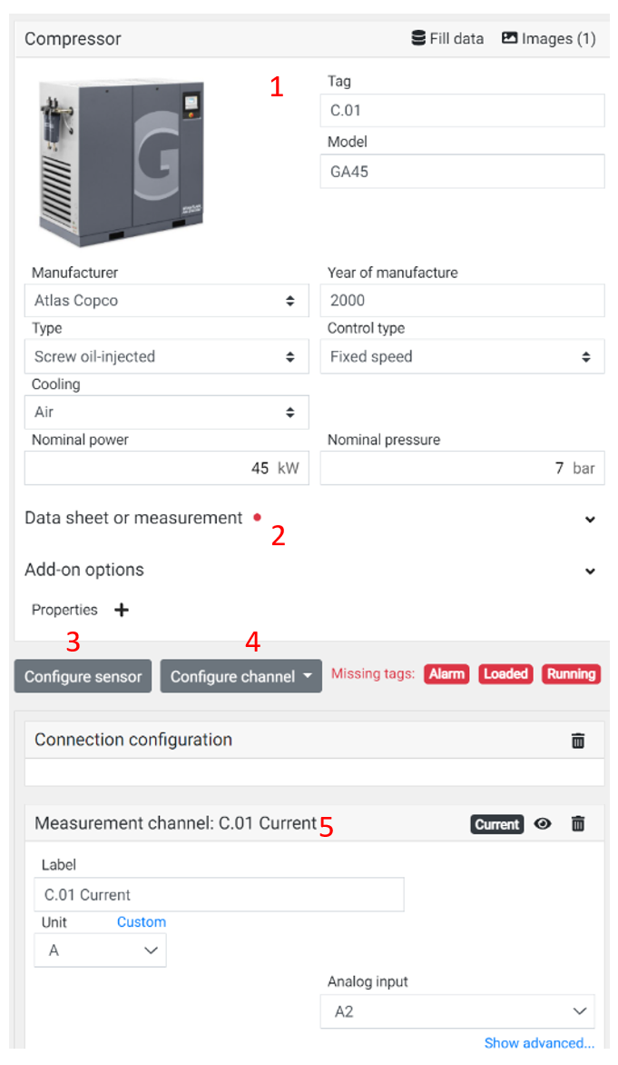
Compressor is an active element that must be fully set with all necessary data in element properties part. Compressor uses some special channels with annotation :
- Loaded
- Running
- Power
- Flow
After you add new compressor please take a picture, prepare technical data-sheet or take a photo of compressor name-plate. You can use also Fill data and pick compressor from different databases (CAGI, OEMs..) or customer own data base.
Under compressor properties you must fill:
Compressor details (you can use Fill database)
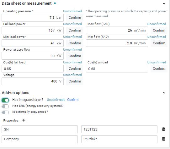
Compressor data-sheets and measurements (power-flow-pressure, voltage, PF…) Those data are very important for calculations and initial benchmarking
select and configure sensor that is used on compressor like CT -amps meter, power meter, compressor controller connection..
Those signal are very important to measure and / or calculate compressor power, flow, loaded and running and alarm signal
Configure channel will guide you through special channels annotations as described above. In some cases CALMS can do this automatically .
User must add also communication configuration in case compressor controller or sensor is using some comm protocols like modbus..
And finally user must do measurement channel configuration
Data sheet or measurement equipment data
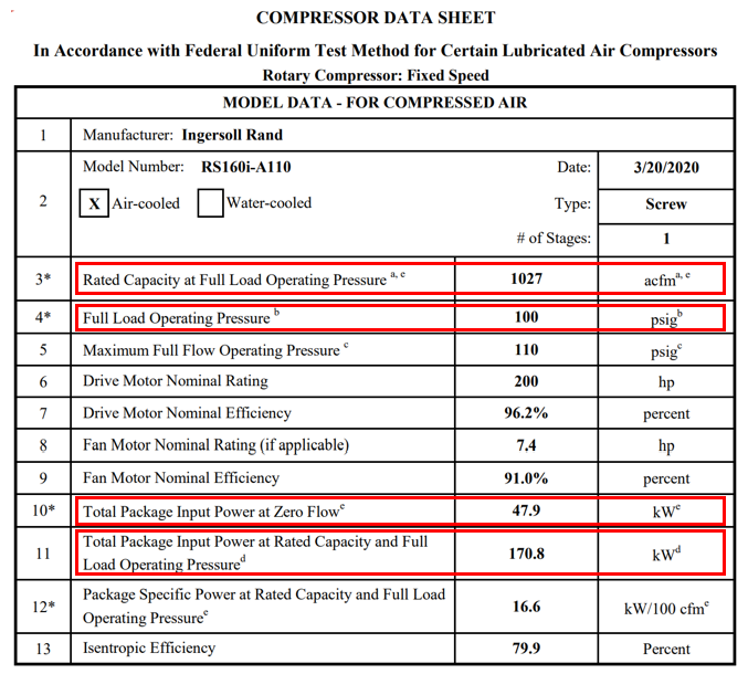
Equipment data are designed and tested performance data that manufacturer put on equipment data sheets. If original data are not available please check CAGI data sheets (be careful to collect correct data - can be different models from different country like 50 or 60Hz).
Insert data from OEM, CAGI or some reliable third party verified data sheet.
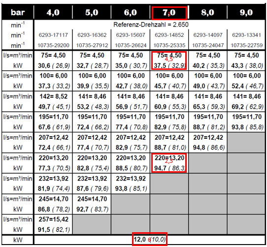
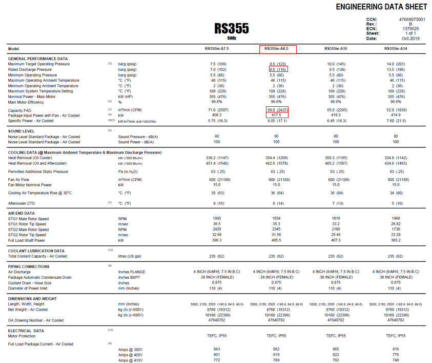
Insert Operating pressure (Full load operating pressure) at which the Max flow (Rated capacity at full load operating pressure)) and Full load power (Total package input power at rated capacity and full load operating pressure) were measured in the datasheet.
Measure electrical voltage and electrical power factor cos(fi) at full load and unload on site.
Example from CAGI data sheets:
Example from OEM data sheet:
Target
Target page is the third part where you have to set all target Key Performance Indicators (KPI) that end user can monitor in Result page with target reference based on baseline or target.
User can add new indicator based on any channel or new calculation with Add indicator button.
The most important KPIs for CALMS are System channels which are channels for complete system. Those channels must be set for each system.
- System pressure
- System flow
- System power
- system specific power SSP
System will suggest also many more predefined indicators
- custom indicator
- total energy consumption TEC
- system energy consumption SEC per unit production
- part of non productive usage-waste PNPU
- reliability
- efficiency
- isentropic efficiency
- compressed air cost
- energy cost for compressed air
- savings opportunity
- CO2 emissions total
- CO2 emissions potential savings
- pressure drop
- dew point
- wet, dry pressure
NOTE: Target values can be set also after one month of active monitoring when baseline can be identified. Pressure Min, Max, setup and critical must be set at system creation because those values are used in many system calculations.
Channels
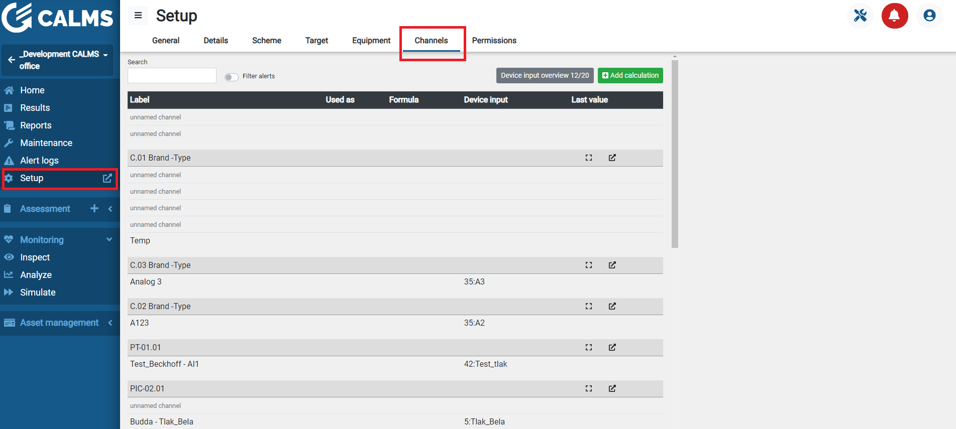
Under channel page system manager can edit advance channel settings, add new channels like calculations, set alerts, alarms and warnings and also set channel as indicator or hide channel on inspect page.
NOTE: When system is created in CALMS and all channels created, system manager can print out SIGNAL LIST and perform field monitoring system setup and Instrumentation Qualification & Operational Qualification (IQ-OQ).
Calculation formula editor
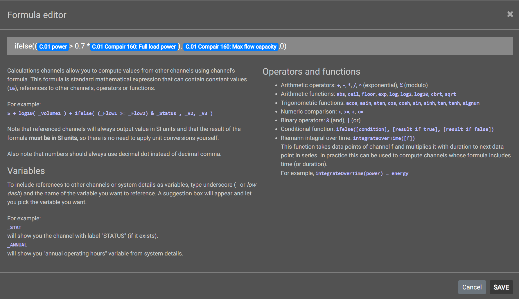
Under channels page or analysis page you can add new calculations with formula editor.
1. Adding calculations
Calculations are very useful tools to get some additional information based on measured data. For example if you are measuring »Pressure before drying equipment« and »Pressure after drying equipment« you can calculate what is the pressure drop and this value you can link to an alarm output so that system notifies you when pressure drop across drying equipment is too high.
Syntax
NOTE:
• In calculation channels only AI, AIP and DI, constants and CI-calculation inputs
• To select existing variable, channel or system constant use underscore sign _
• Maximal length of calculation formula is 255 characters;
• Calculations become active when they are defined ( if we define calculation today,
system will not calculate values from past but will start calculate from the time calculation is defined);
• Also when we »Edit« calculation the correction will apply from time calculation is edited.
1. Operators
• + (addition)
• - (subtraction)
• * (Multiplication)
• / (Division)
• ^ (Exponentiation)
• % (Modulo)
2. Comparison operators
• > (greater then)
• < (less than)
• >=, <= (greater or equal to, less or equal to)
• & (AND operator)
• | (OR operator)
3. Functions
• Ifelse
• abs: absolute value
• acos: arc cosine
• asin: arc sine
• atan: arc tangent
• cbrt: cubic root
• ceil: nearest upper integer
• cos: cosine
• cosh: hyperbolic cosine
• exp: euler’s number raised to the power (e^x)
• floor: nearest lower integer
• log: logarithm (base e)
• log10: logarithm (base 10)
• log2: logarithm (base 2)
• sin: sine
• sinh: hyperbolic sine
• sqrt: square root
• tan: tangent
• tanh: hyperbolic tangent
• signum: signum function
Examples
• We can define new calculation channel with simple formula: »AI1 + AI2« .That means system will sum up values from AI1 and AI2.
• We can also use AIP’s channels to calculate total power of the system: »AIP1 + AIP2 + AIP3 + AIP4«. System will sum up powers from compressors 1 to 4.
• Lets calculate total specific power in kWh/m3: »(AIP1+AIP2+AIP3+AIP4)/(AI2*60)«, where AIP1+AIP2+AIP3+AIP4 is total power of the system and AI2 is measured flow in m3/min
• We can also use DI’s channels for some Boolean operations: »DI1 & DI2«. The result is 1 (True) if DI1 and DI2 are true. The result is 0(False) if one of them is false.
• Ifelse function. We can also calculate capacity of the ON/OFF compressor based on ifelse function. Example: We have 160kW ON/OFF compressor 2 with 32,3 m3/min output capacity. Formula is: »ifelse((AIP2>130),32.3,0)«. Result is 32 if compressor’s power is greater than 130kW, if power is less than 130 kW result is 0.
Most typical sample calculations
• Calculate »Flow« (from air speed measured by a flowmeter):
Formula: ((3.14*D^2)/4)_AI2_60 [m3/min],
- D=inner pipe diameter [m],
- AI2=measured speed [m/s].
• Calculate »Compressor power« from measured current:
Formula: *_(AI3Voltage_sqrt(3)PF) [kW],
          AI3=measured current \[A\],

          Voltage=Line voltage \[V\],

          PF=Power factor (cosfi).
• Calculate «Compressor power« from measured current with different cosfi for
loaded/unloaded compressor state:
Formula: **ifelse((DI1), (AI3*Voltage*sqrt(3)*PF1),(AI3*U*sqrt(3)*PF2))**,\[kW\]

          AI3=measured current \[A\],

          Voltage=Line voltage \[V\],

          PF1=Power factor (cosfi) at loaded state,

          PF2=Power factor (cosfi) at unloaded state,

          DI1=digital input that is TRUE when compressor is loaded.
Channels alerts
Under Setup/Channels page when you select channel you can add as many alerts as you want with button Add alert.

CALMS is using two types of alerts linked to channels:
- Warning
- Alarm
For each alert select trigger- When value (is lower, equal or higher) enter trigger value and select alert type (warning, alarm).
Under Advanced options set
Ignore alerts shorter then (time)
Merge alerts that are less then (time) apart
CALMS will send alert to selected participant (all system users) on Email, SMS-text or application notification bar. Each user can set alert under Users/notificationsmenu.
Alerts are handled and acknowledge in Alert logs page.
Channel target
Under Setup/Channels page when you select channel you can add or manage targets (KPI) with button Add target.
NOTE:
Targets are set on monthly baseline period. In case you have daily target (recalculate for monthly target value (30 days)
Targets and KPI (Key Performance Indicators) are managed on Target page.
Permissions
System manager can add new users or invite new users to CALMS system and add them with selected roles and permissions. System owner can add also expert to the system for audit. In case system owner can add also CALMS support user to help with system issues.
User can have different roles that have predefined permissions.
- owner
- assessment
- monitoring
- expert
- custom
Permissions can be set only by system owner and will grant access for CALMS functions:
- edit setup
- edit permissions
- assessment: view, survey, repair, delete, create
- monitoring: view, manual, analysis, simulation
- asset : events, TCO, compressor database, equipment


