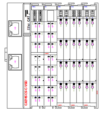
8 – HMI OP OPERATOR PANEL OVERVIEW
PM-2 and PM-4 are using smaller 4,3’’ HMI, PM-8 is using bigger 7’’ HMI.
4,3’’ HUMAN MACHINE INTERFACE (FOR PM-2 AND PM-4)
STATUS SCREENS
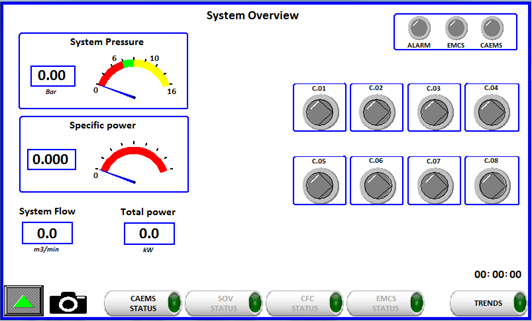
CAEMS can be ordered with an optional HMI operator panel. When powering
up the unit the operator panel (OP) will display the HOME screen.

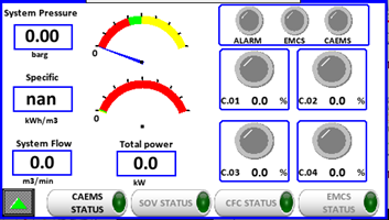
Pressing the icon will send you to the CAEMS status menu. Here you have
an overview of your sistem. The squares on the right represent ALARM,
EMCS, CAEMS and compressors status.

If any of the states in the upper right corner is active the signal
lights will lid up. Below is a picture to represent the status light
color. Alarm LED is ON when system alarm is active. Which alarm is
active you can check in Alarm status page.EMCS light is ON if EMCS
Control feature is enabled. CAEMS light is ON if CAEMS is activated in
general settings, pressure is beyond critical and at least one
compressor is running.
 In the right corner below there are 4 status light to indicate single
compressor state. Compressor states are:
In the right corner below there are 4 status light to indicate single
compressor state. Compressor states are:


STOPPED RUNNING LOADED
ALARM!
Below compressor state light you can see temporary % load of the
compressor. If compressor is VSD and it is running loaded this % changes
from 0-100%. If compressor is ON/OFF and it is running loaded this %
indicates full load (100%). If compressor is running unloaded or is
turned off this % indicates no load (0%)
You can navigate the menu by pressing any of the avaliable
 buttons. To return to home
page press the button.Pressing the button will activate the CAEMS
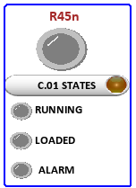
status menu, which is composite by several different pages:On the first
status page compressor digital states are visible.
buttons. To return to home
page press the button.Pressing the button will activate the CAEMS
status menu, which is composite by several different pages:On the first
status page compressor digital states are visible.
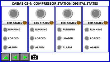
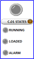
If any state is active, the lights will turn on in color, otherwise the
displayed color is gray. Upper light represent the same states as
in REVIEW page.
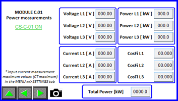
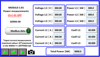
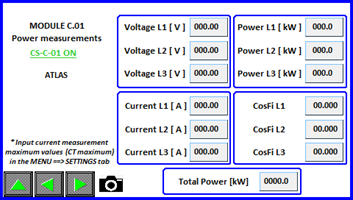
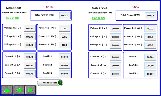
You can jump directly to compressor power analyzer state by pressing the name close to the compressor symbol. On the PM-X there are 4 compressor power measurement pages. Here are displayed power related measured values.Notice the CAL-C-X text . If the text is colored GREEN a CAEMS compressor module is connected and recognized, otherwise the text color is RED!
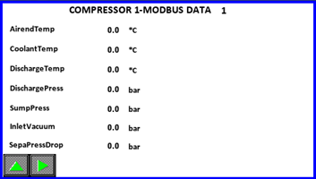
If compressor has enabled MODBUS communication an extra button is
displayed. By pressing this button you enter to compressor MODBUS
parameters pages.
Here are three MODBUS pages. How many parameters is shown depends which
controller is selected. (See belowàCompressor settings). On first page
you can see first 14 parameters.
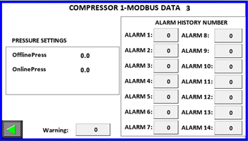
On last third page you can se pressure parameters, alarm and warning
codes for further analysis
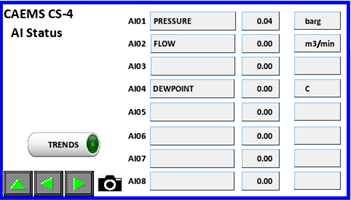
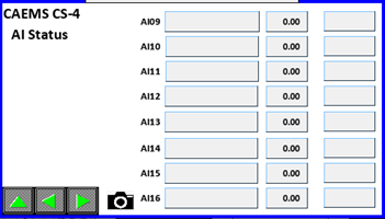
The second page of the CALMS STATUS group represents CALMS PM-X digital input states. Each PM has by default eight digital inputs. If a digital state is active the representing light will light up.
Pressing the up button from this screen will show the main selection
screen, otherwise pressing will show the next/previous screen. The
analog inputs screen displays values that needs to be entered in the
SETTINGS menu. When settings are completely filled, the input tags and
measurement values will be displayed in real time as in picture above.
Here you can also access to TRENDS menu. Moving trough the menu is
achieved by pressing the buttons.
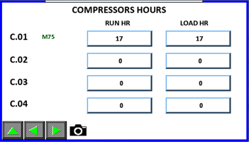
Next page indicates compressors hours. Hours are calculated via running
and loaded signals or via MODBUS states if enabled. The hours can be
corrected by clicking on fields, but you have to be login as manager.
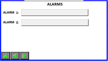
Next page shows us active alarms. If no alarm is present the fields are empty. Possible alarms are:Critical pressure, AI probe alarm, DI alarm, Voltage Imbalance alarm, Compressor 1-8 alarm, C.01 to C.08 alarm and EMCS Fault Compressor 1-8.
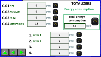
Next page shows energy consumption totalizers. System calculates energy
consumption for each compressor and for additional fourAi’s that can be
selected in CALMS settings (login as operator required). Total energy
consumption is sum up of all compressors and additional 4 AI’s energy
consumptions. You can reset each energy consumption by pressing button
(press and hold for 1 sec, login as operator required).
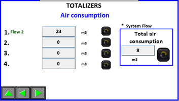
Next page shows air consumption totalizers. System calculates air consumption for selected System flow (this can be selected in CALMS settings Meter display settings, login as operator required) on HMi visible as Total air consumption and also calculates totalizers for additional four Ai’s which are calculated independately of total air consumption. (if you have flowmeter installed on one of production lines and you want to know what is the air consumption of this line, you select this AI as additional AI for air consumption totalizer)
Next page will display MODULE C.01 power management, next MODULE C.02
power management and so on ..
Returning to the REVIEW page is done by pressing the up button.
By clicking on you will enter the Shut Off Valves status menu. NOTE:
This feature must be enabled to be possible to enter those status
menus.Here you can see statuses of all three SOV. Red or green color of
specific valve ( , ) tells us if specific SOV is enabled or disabled.
Red color means that this SOV is disabled (its regulation is disabled),
green color means that this SOV is enabled (its regulation is
enabled).Each SOV is recognized through “SOV Name” which is given in SOV
settings (must be logged in as Operator). Each SOV can be in AUTO or
MANUAL mode. Manual mode means that valve can be opened or closed via
HMI interface by switching the Open-Close switch. If SOV is in AUTO mode
means that valve is opening, closing via schedule which is set on daily
base.Position of SOV indicates the position of specific SOV.
 Returning to the REVIEW page
is done by pressing the up button. By clicking on you will enter the
CFC Status page. NOTE: This feature must be enabled to be possible to
enter those status menus.
Returning to the REVIEW page
is done by pressing the up button. By clicking on you will enter the
CFC Status page. NOTE: This feature must be enabled to be possible to
enter those status menus.
On CFC Status page we can see all the vital system and CFC
parameters.(Statuses of compressors, position of CFC valves, Inlet and
Outlet pressure, Setpoint value and System flow. On the top of the
window is a status bar which indicates if which regulation mode CFC is.
Here is in MANUAL mode. That means CFC valves can be regulated manually
via HMI interface in CFC Settings (must be logged in as operator).
Returning to the REVIEW page is done by pressing the up button. By
clicking on you will enter the EMCS Status page. NOTE: This feature
must be enabled to be possible to enter those status menus.On first EMCS
status page you can see all the compressors states (Compressor stopped,
loaded, unloaded, alarm, remote control enabled). You can also see what
is the pressure status and what is the ECMS status. EMCS status tells us
what EMCS function is doing, for example: loading new compressor,
starting new compressor,…On the top right corner we can see what is the
enabled control mode (Priority mode, Energy mode or Schedule mode).
You go to next page by clicking icon. On next page you can see actual
compressors stop and start priority.
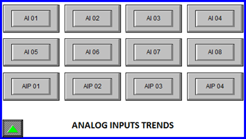
TREND SCREEN
By pressing the button it will show the Analog inputs trends screen.
Here you will be able to investigate a single AI values at desired
time. Pressing the up button from this screen will show the main
selection screen.
When any AI0X button is pressed the following screen will be shown
: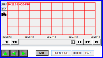
Pressing the up button from this screen will show the TRENDS selection
screen. Buttons will move to previews/next analog input trends. In the
upper left corner you will find a camera icon . Pressing it will save a
print screen of the opened page. Right to the forward button is
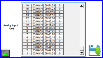
displayed the analog input number/name . Pressing it will open a history
window from witch you will be able to safe a csv file of the input
values by pressing the save icon ( save to USB if present ).
Returning to the main selection screen is performed by repetedly
pressing the up button.
ALARM SCREEN
By pressing the button will show the ALARM screen
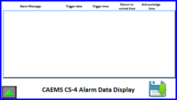
Here you will be able see any alarm that has been recorded by the CALMS
system. Alarms must be acknowledged by pressing on the alarm text (text
color with turn to green). Pressing the up button from this screen will
show the main selection screen
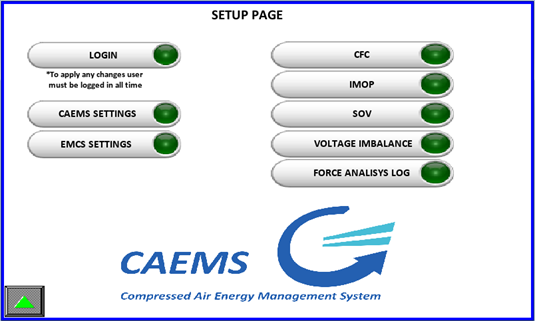
SETUP
Next on the main window is the SETUP icon . Pressing it will show the
SETUP page.
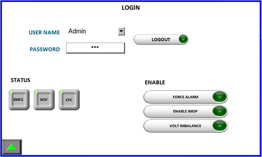
LOGIN SCREEN
Before you can actually enter or enable any setting a operator login is
mandatory. This is done by the following procedure.By pressing the
button in the main manu you will be showed the login screen. Here you
can see which functions are purchased and
enabled.
Operator is to be select by a dropdown menu,
Password is to be inputed by user. Prior to that any change is
uneditable.
After succcesfull login additional options can be enabled. Enabling the
option will be seen by activity light and text change. Please notice
that not all option are avaliable. Which options will be avaliable is
determined by the option your CALMS is shipped. In the picture below
CFC,EMCS and SHUTOFF VALVE options are purchased therefore are all
avaliable to use.
Pressing the up button from this screen will show the SETUP screen.
After enabling additional options the SETUP page menu looks different:
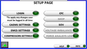
CALMS SETTINGS SCREEN
By pressing the button will show the SETTINGS screen. There are several
screens where you can input system settings.
CALMS PM-X ANALOG STATES SETUP
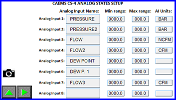
Here you MUST input Analog inputs name, min values, max values and
measuring units. Pressing on an empty box under Analog input name or AI
Units opens a keyboard.
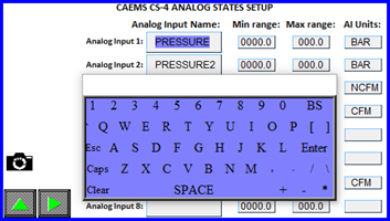
After entering desired text press the Enter button to confirm input and
hide keyboard, or ESC to cancel inputs and hide keyboard. Pressing the
gray button under the Minimum or Maximum AI range will open a numerical
keyboard for entering numerical
data.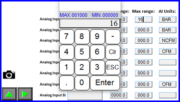
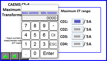
Current transfomer range must be entered here for each CAL-C module (Compressor). Buttons in the lower left corner still have the same functionality as on other screens.
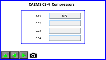
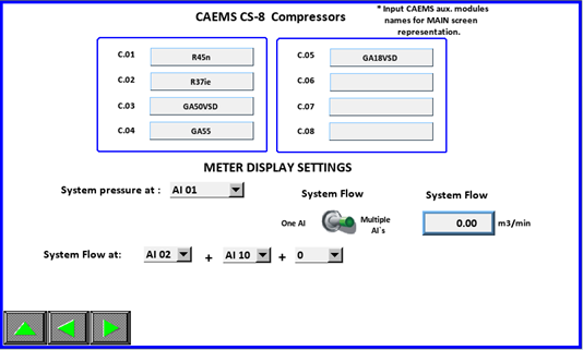
COMPRESSOR NAMES
Compressor names can be given names through this input page.
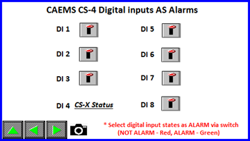
Here you can choose which DI`s you will use as ALARM inputs. If
specific DI is used as ALARM means that after 5s of active state alarm
output DO4 will be activated and also CALMS Alarm will be triggered.
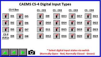
Depending on what type of digital input you need (NO, NC) different
inputs states and logic can be selected here. Here you can set for all
DI’s that are available in your device.
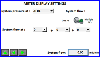
METER DISPLAY SETTINGS
Here you can choose, depending on which AI is your system pressure, the
correct AI. Same for system flow. In case system flow is on multiple
AI`s you select “Multiple AI`s” and choose correct analog inputs. Sum
of all AI`s is your system flow from which Specific power is
calculated.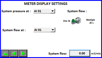
If you don’t have connected flowmeter to any of AI’s you can choose
“Calc Flow” and system will calculate the flow. In this case nominal
flow of compressors must be set correctly, otherwise calculation of flow
will not be correct. Here you can also check what is the MAX RANGE of
calculated flow. Default value is 300 m3/min. If necessary it can be
changed, but you have to be login as Manager. This MAX Range value is
value which is set on CALMS WEB interface as MAX Range of AI21. (AI21 is
reserved for calculated
flow)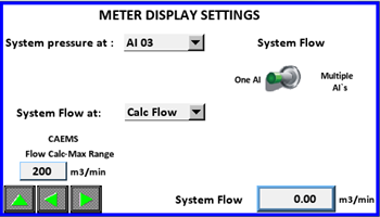
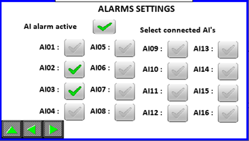
ALARM SETTINGS
Here you can choose which analog inputs are connected to 4-20mA sensors.
System will than constantly checking those inputs. In case of under or
over current of the analog input alarm will be triggered.
UNIT SELECTION
On unit selection page you can adjust units for pressure, flow,
specific, temperature and volume. This settings must be set correctly
and same units must be used on analog input settings page, because
system is doing some calculations based on those
settings.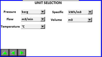
TOTALIZERS
On this page you can adjust four additional analog inputs for totalizer
calculation. Adjust four additional AI’s for energy consumption which
will be added to total energy consumption ( compressors energy
consumption + additional AI’s energy consumptions = total energy
consumption). Adjust four additional AI’s for air consumption, which are
independently calculated and have no relation with total air consumption
which is based on system flow measurement. If none is selected means
that system will not calculate certain additional
TOTALIZER. 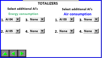
GENERAL SETTINGS
Here you can acess the HMI setting page and enable or disable the PM-X functionality.Minimal critical pressure is used to automatically set PM-X ENABLE/DISABLE button to off if pressure is under that value and all compressors are shutdown. Line voltage setting is used for power calculation ( see below). You can also choose energy specific display or power specific display.
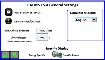
On this page users can select HMI display language by language selector
:
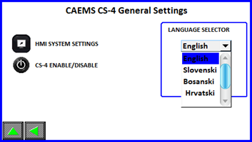
Depending on user location and expected language the selection can be
upgraded. After finishing the setting up of the input return to SETUP
page by pressing the button.
EMCS SETTINGS
If EMCS is purchased and enabled in login page you can acess EMCS
SETTINGS by pressing the EMCS SETTINGS button and a setup screen for
the control system will be displayed. Here you can input EMSC options
such as control pressure, timers and control
mode. Navigate the pages with
the navigation buttons as usual.
Navigate the pages with
the navigation buttons as usual.
PRESSURE SETTINGS
On this page user setups EMCS pressure parameters.PRESSURE SETPOINT:
is the desired pressure of the systemCRITICAL PRESSURE: is the
minimum pressure of the system. If pressure goes below that point an
alarm will be issued and additional compressors will be
started.PRESSURE SETPOINT OFFSET: is the below and under Pressure
Setpoint setting. If pressure reaches (Pressure Setpoint + Pressure
Setpoint Offset) next compressor will be unloaded and if pressure
falls below (Pressure Setpoint - Pressure Setpoint Offset) next
compressor will be loaded.MAX. CRITICAL PRESSURE: If pressure
reaches this set value emergency stopping of compressors is followed.On
this page you can also select on which AI is connected pressure sensor
for EMCS regulation.
If pressure settings are setup as above the EMCS will try to maintain a
system pressure between 7,5 and 6,5 bar. If pressure goes higher
compressor will be unloaded, if pressure falls below next compressor is
loaded.
TIMERS
On this page user setups EMCS TIMER settings:NORMAL START: time that
EMCS will wait before starting compressor in the system if system
pressure falls below (Pressure Setpoint - Pressure Setpoint
Offset).CRITICAL START: time that EMCS will wait before starting
another compressor if system pressure falls below critical pressure set
pointLoad/Unload: time that EMCS will wait before loading or
unloading next compressor.Unload Stop(long): time in which next
unloaded compressor will be stoppedUnload Stop(short): time in which
next unloaded compressor will be stoppedDifference between long/short
timer is in the number of unloaded compressor. If only two or less
compressors are unloaded than long timer is used, otherwise short timer
is used.Delay between starting: time that EMCS will wait unit
starting next compressor (normal and critical conditions)
IMPORTANT! PRIORITY MUST NOT BE SET AS ZERO. TWO COMPRESSOR CAN’T HAVE
SAME PRIORITY NUMBER!!!Compressor with the HIGHEST starting priority
number will be started FIRST, compressor with LOWEST starting priority
number will be started last.Compressor with the HIGHEST stopping
priority number will be stopped FIRST, compressor with LOWEST stopping
priority number will be stopped last.
EXAMPLE: PM-4 Each priority consists of 4 digits ( PM-4) or 8 digits (CS-8). First digit represents priority number of first compressor (C.01) in the system, second digit represents second compressor (C.02) in the system, third digit represents third compressor (C.03) in the system, fourth digit represents fourth compressor (C.04) in the system.** Starng priority: 234Stopping priority**: 2143In upper
example compressor four (C.04) is first to be started/loaded and
compressor three (C.03) is last (fourth) to be started/loaded. When we
are unloading/stopping compressor and we refer on upper stopping
priority we see that compressor two (C.02) is first to be
stopped/unloaded and compressor three (C.03) is last (fourth) to be
stopped/unloaded.
CONTROL MODE
Here you select desire control mode. Only one mode can be selected. You
can adjust settings of control mode by clicking on specific icon. You
can click the icon before enabling specific control mode.
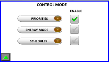
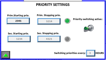
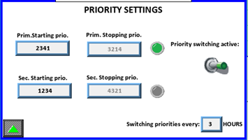
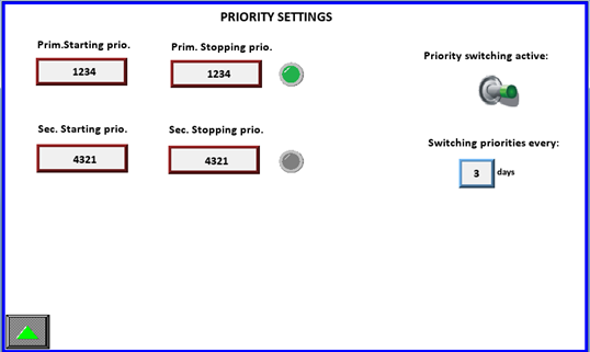
PRIORITIES
In this control mode you have two possible options. One option is to
adjust only Primary Starting Priorities and Primary Stopping
Priorities. You can also enable Switching Prio option and system
will then change the compressors priorites every defined hours.The LED
shows us which priorities are used at the momentàPrimary or secondary.
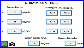
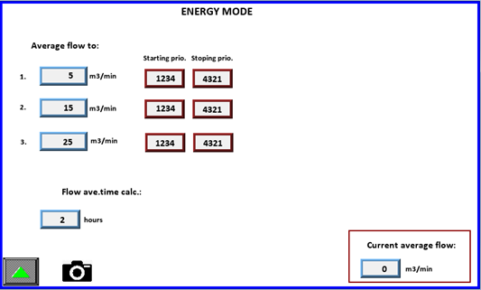
ENERGY MODE SETTINGS
Input your flow values and priorities will be acceppted if system flow
is in determined range. Determine the flow average time calculation.
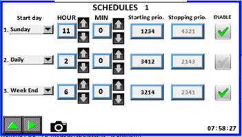
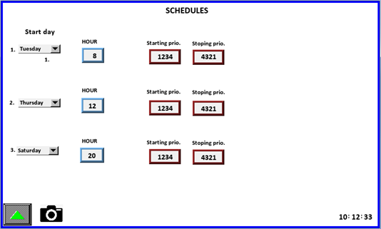
SCHEDULES
You can input nine different schedules. When specific schedule is active
the correct priorities will be accepted. Operator can set the start day,
hour, min, starting priorites and optional stopping priorites. With
enabling certain schedule the system will start using those
settings.** START DAY:** Operator can choose from Monday, Tuesday,
Wednesday, Thursday, Friday, Saturday, Sunday, Daily, Week Day
(Monday-Friday), Week End (Saturday, Sunday).HOUR: 0-23 (can only be
sleected by )MIN: 0-59 (can only be selected by )If two schedules
have the same start day, hour and min the higher numbered schedule
will have priority.
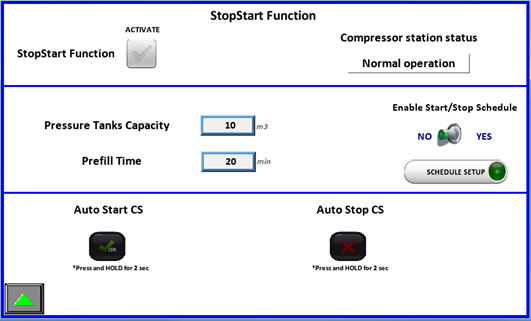
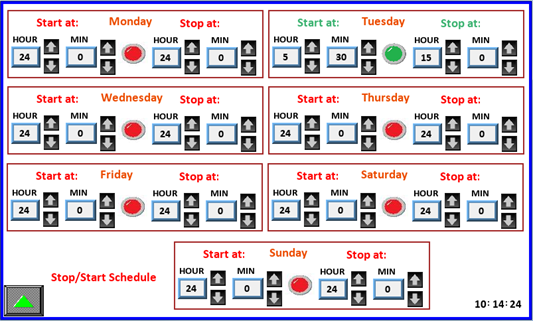
Compressor System Stop-Start FUNCTION
On this page user can stop and start whole COMPRESSOR SYSTEM (CS). By activating this function system will calculate how many compressors are needed to fill the system in prefill time specified by operator. So, when “Auto Start CS” button is pressed, system starts compressors ( how many is calculated from “Pressure tank capacity” and “Prefill time”). When pressing “Auto Stop CS” all compressors will be stopped and system will wait for next command to start CS.
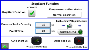
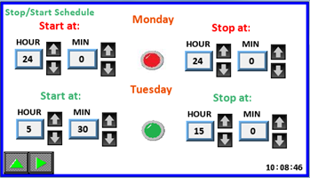
If Start/Stop schedule is enabled, operator has option to adjust
schedule when CS will start and when stop. On picture below we see that
schedule for Monday is disabledàRed LED (If hour for start and stop is
24 then schedule for this day is disabled). For Tuesday we see that
schedule is enabledàGreen LED and time is set. Compressor station will
start at 5.30 and stop at 15.00.Here you can adjust schedule for each
day.
After finishing setup return to the SP page by pressing the UP button.
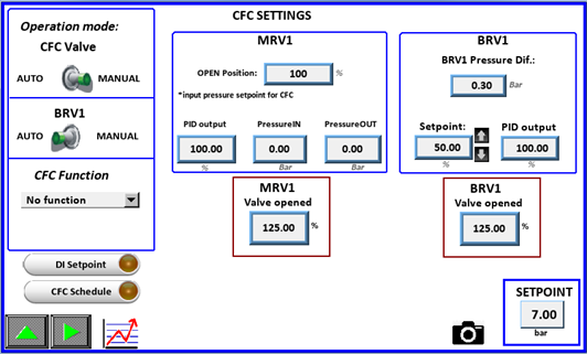
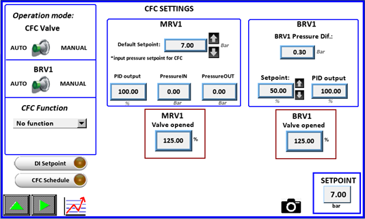
CFC SETTINGS
From the SETUP PAGE, if the option is purchased and enabled pressing the
button enters the CFC menu.Here is the main setting page for CALMS
Flowcontroller (CFC). Operation mode can be Manual or Auto. In Manual
mode we can manually open MRV1 valve from 0-100% in order to test its
functionality.
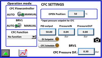
In Auto mode we set the Setpoint value of Pressure that we want to
maintain after Flowcontroller. We have Default setpoint which is used if
there is no other CFC Function selected, otherwise other Setpoints are
used.Also for BRV1 valve we have Manual or Auto mode. In Manual mode we
can also manually open BRV1 valve from 0-100% in order to test its
functionality. In Auto mode we adjust the CFC Pressure Diference. If
pressure falls below Setpoint-CFC Press. Diference CFC opens in
order to raise outlet pressure
.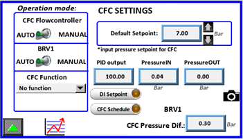
With clicking on icon you are redirected to CFC status page, which is
described in upper pages
System offers to set the Setpoint for CFC from two different functions.
If none function is selected Default Setpoint is used.
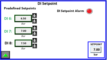
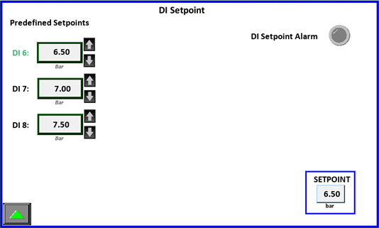
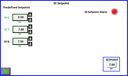
DI Setpoint Function
Here we can set Setpoint via three digital inputs which are predefined
(DI6, DI7, DI8). When certain DI is activated it turns green and at the
bottom on right side you can see which Setpoint is used at the
moment.
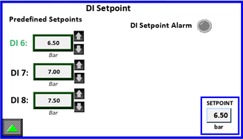
Only one DI can be activated at once otherwise DI Setpoint Alarm is
triggered and Default Setpoint is used.
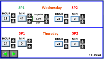
CFC Schedule Function
Here you can adjust schedule for CFC. For each day you can adjust two
different setpointsà SP1 and SP2. When specific Setpoint is used
it turns green. If time adjustments are not OK (if hour setting is 24,
or both SP of the same day have set same time) the setting for Setpoint
disappears and system will not use this SP.
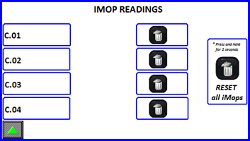
IMOP
Pressing the button enters the IMOP menu. A readings reset button per
compressor is available. IMOP is a function that monitors and writes
values of all AIP variables (all voltages, all currents, all CosFi-s,
reactive power, real power,…) in CSV format and uploads it. If
compressor is ON/OFF type it writes and uploads both states in
difference from VSD compressors for which writes and uploads only one
state à RUNNING. By resetting IMOP readings will be performed and
uploaded again
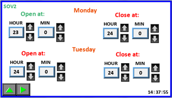
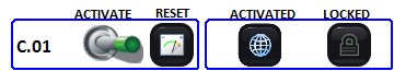
SHUTOFF VALVE SETTINGS
Pressing the button enters the SHUT OFF VALVES menu. If this option is
purchased, operator can set three different shut off valves. They can be
regulated manually ( open-close ) or automatically through schedule
setup. We also can set the name of each valve for easier
recognization.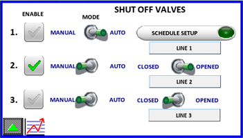
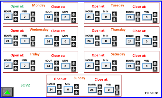
If we want to set the schedule, we click on and then adjust schedule
settings for specific Shut off valve. When is green it means that second
SOV is enabled, otherwise its regulation is disabled.
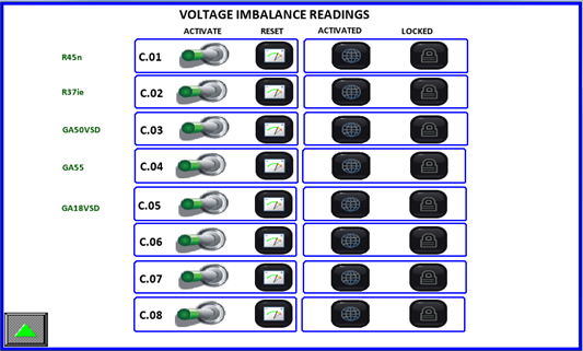
VOLTAGE IMBALANCE
Pressing the button enters the specific menu. Here you can view
function status, activate readings and reset all voltage imbalance
readings. Voltage imbalance is a function that uploads an alarm log file
when supply voltage varies for more than 3% from rated voltage. When
first event happens, a timer of 300 s starts and after the expiry
function waits for next voltage imbalance. After third event of
imbalance the function locks and waits for manual reset on HMI. If the
LOCKED icon is active a reading has already been uploaded. Press and
hold the reset button to reactivate reading and uploading data.

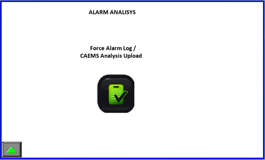
ANALISYS LOG FUNCTION
Pressing the button enters the LOG menu. When you activate this
function, system uploads all values of all variables from 1 minute
before and 1 minute after the function has been activated.
INFO & HELP SCREEN
The remaining buttons on the main selection screen display Info and Help for the CALMS – CAL interface.
EVENT LOG
From main menu go to event log page by pressing the icon. Event log is
self-explanatory.
ALARM LOG
From main menu go to alarm log page by pressing the icon. Alarm log is
self-explanatory.
9 HUMAN MACHINE INTERFACE (FOR PM-8)
STATUS SCREENS
CALMS can be ordered with an optional HMI operator panel. When powering
up the unit the operator panel (OP) will display the HOME screen.

Pressing the icon will send you to the CALMS status menu. Here you have
an overview of your sistem. The squares on the right represent ALARM,
EMCS, CALMS and compressors status.
If any of the states in the upper right corner is active the signal lights will lid up. Below is a picture to represent the status light color. Alarm LED is ON when system alarm is active. That means if pressure is below critical value, if any of compressors is in alarm or one of auxilliary CAL-C modules is disconnected.EMCS light is ON if EMCS Control feature is enabled. CALMS light is ON if CALMS is activated in general settings, pressure is beyond critical and at least one compressor is running.

In the right corner below there are 8 status light to indicate single
compressor state. Compressor states are:
STOPPED RUNNING LOADED ALARM


You can navigate the menu by pressing any of the avaliable buttons. To
return to home page press the button.Pressing the button will activate
the CALMS status menu, wich is composite by several different pages:On
the first status page compressor digital states are
visible.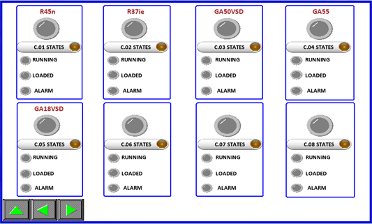
If any state is active, the lights will turn on in color, otherwise the
displayed color is gray. Upper light represent the same states as in
REVIEW page. On the top you can also see name of the compressor.
You can jump directly to compressor power measurement by pressing the On the PM-8 there are 8 compressor power measurement pages. Here are displayed power related measured values.Notice the CAL-C-0X text . If the text is colored GREEN a CALMS module is connected and recognized, otherwise the text color is RED!
If compressor has enabled MODBUS communication an extra button is
displayed. By pressing this button you enter to compressor MODBUS
parameter pages.
In MODBUS parameter page you can see detailed compressor performance.
How many parameters is shown depends what is the type of the compressor
controller.
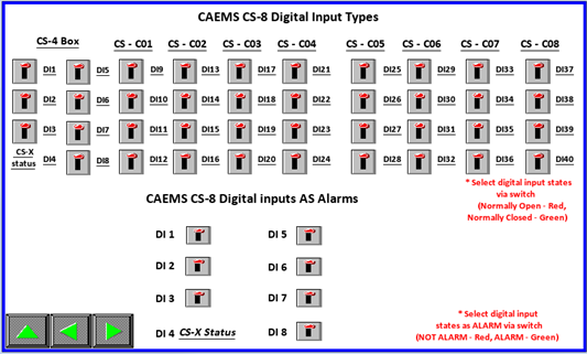
The second page of the CALMS STATUS group represents CALMS PM-8 analog and digital input states. Each PM has by default eight digital and eight analog inputs. If a digital state is active the representing light will light up.The analog inputs screen displays measured values. When settings are completely filled, the input tags and measurement values will be displayed in real time.You can also check AI Probe alarm. This light will become red if any of connected sensors is faulty. (it must be set in settings)
Pressing the up button from this screen will show the main selection
screen, otherwise pressing will show the next/previous screen. On next
4 status pages you can see power analyzer values for each
compressor.Next status page is compressors hour status page. Hours are
calculated via running and loaded signals or via MODBUS if enabled. The
hours can be corrected by clicking on fields, but you have to be login
as manager.
Returning to the REVIEW page is done by pressing the up button.

By clicking on you will enter the Shut Off Valves status menu. NOTE:
This feature must be enabled to enter those status menus.Here you can
see statuses of all three SOV. Red or green color of specific valve ( ,
) tells us if specific SOV is enabled or disabled. Red color means that
this SOV is disabled (its regulation is disabled), green color means
that this SOV is enabled (its regulation is enabled).Each SOV is
recognized through “SOV Name” which is given in SOV settings (must be
logged in as Operator). Each SOV can be in AUTO or MANUAL mode. Manual
mode means that valve can be opened or closed via HMI interface by
switching the Open-Close switch. If SOV is in AUTO mode means that valve
is opening, closing via schedule which is set on daily base.Position of
SOV indicates the position of specific
SOV.
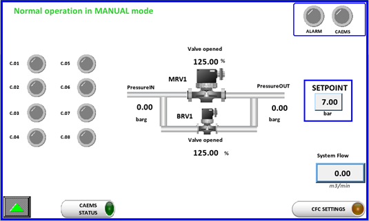
Returning to the REVIEW page is done by pressing the up button. By
clicking on you will enter the CFC Status page. NOTE: This feature
must be enabled to be possible to enter those status menus.On CFC Status
page we can see all the vital system and CFC parameters.(Statuses of
compressors, position of CFC valves, Inlet and Outlet pressure, Setpoint
value and System flow. On the top of the window is a status bar which
indicates if which regulation mode CFC is. Here is in MANUAL mode. That
means CFC valves can be regulated manually via HMI interface in CFC
Settings (must be logged in as operator)
.
Returning to the REVIEW page is done by pressing the up button. By
clicking on you will enter the EMCS Status page. NOTE: This feature
must be enabled to be possible to enter those status menus.On first EMCS
status page you can see all the compressors signals, system pressure and
system flow.
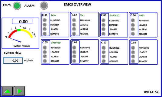
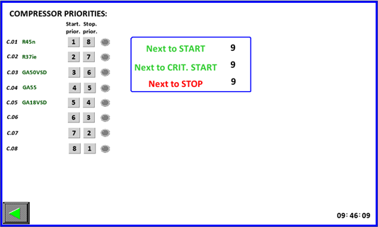
You go to next page by clicking icon. On next page you can see
compressors priorities and which compressor is next to start and stop.
Number 9 means that there is none compressor to regulate.
TREND SCREEN
By pressing the button from system overview page it will show the
Analog inputs trends screen. Here you will be able to investigate a
single AI values at desired time.
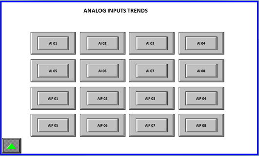
When any AI0X button is pressed the following screen will be shown:
Pressing the up button from this screen will show the TRENDS selection
screen. Buttons will move to previews/next analog input trendsReturning
to the main selection screen is performed by repetedly pressing the up
button.
ALARM SCREEN
By pressing the button will show the ALARM screen.
Here you will be able see any alarm that has been recorded by the CALMS
system. Alarms must be acknowledged by pressing on the alarm text (text
color with turn to green). Pressing the up button from this screen will
show the main selection screen.
SETUP
Next on the main window is the SETUP icon . Pressing it will show the
SETUP page.
LOGIN SCREEN
Before you can actually enter or enable any setting a operator login is
mandatory. This is done by the following procedure.By pressing the
button in the main manu you will be showed the login screen. Here you
can see which functions are purchased and
enabled.
Password is to be inputed by user. Prior to that any change is
uneditable.
After succcesfull login additional options can be enabled. Enabling the
option will be seen by activity light and text change. Please notice
that not all option are avaliable. Which options will be avaliable is
determined by the option your CALMS is shipped. In the picture below
CFC,EMCS and SHUTOFF VALVE options are purchased therefore are all
avaliable to use.
 Pressing the up button from this screen will show the SETUP screen.
After enabling additional options the SETUP page menu looks different:
Pressing the up button from this screen will show the SETUP screen.
After enabling additional options the SETUP page menu looks different:
CALMS SETTINGS SCREEN
By pressing the button will show the SETTINGS screen. There are several
screens where you can input system settings.
Here you MUST input Analog inputs name, min values, max values and measuring units. Current transfomer range must be entered here for each CAL-C module (Compressor). Pressing on an empty box under Analog input name or AI Units opens a keyboard.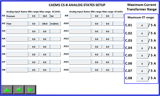
COMPRESSOR NAMES AND METER DISPLAY SETTINGS
Compressor names can be given names trought this input page. Here you
can choose, depending on which AI is your system pressure, the correct
AI. Same for system flow. In case system flow is on multiple AI`s you
select “Multiple AI`s” and choose correct analog inputs. Sum of all
AI`s is your system flow from which Specific power is calculated.
 If you don’t have connected flowmeter to any of AI’s you can choose
“Calc Flow” and system will calculate the flow. In this case nominal
flow of compressors must be set correctly, otherwise calculation of flow
will not be ok. Here you can also check what is the MAX RANGE of
calculated flow. Default value is 200 m3/min. If necessary it can be
changed, but you have to be logined as Manager. This MAX Range value is
value which is set on CALMS WEB interface as MAX Range of AI21. (AI21 is
reserved for calculated flow)
If you don’t have connected flowmeter to any of AI’s you can choose
“Calc Flow” and system will calculate the flow. In this case nominal
flow of compressors must be set correctly, otherwise calculation of flow
will not be ok. Here you can also check what is the MAX RANGE of
calculated flow. Default value is 200 m3/min. If necessary it can be
changed, but you have to be logined as Manager. This MAX Range value is
value which is set on CALMS WEB interface as MAX Range of AI21. (AI21 is
reserved for calculated flow)
Here you can choose which DI`s you will use as ALARM inputs. If
specific DI as ALARM is used it means that after 60s of active state
alarm output DO4 will be activated and also CALMS Alarm will be
triggered.Depending on what type of digital input you need different
inputs states and logic can be selected here. Here you can set for all
DI’s that are available in your device.
ALARM SETTINGS
Here you can choose which analog inputs are connected to 4-20mA sensors.
System will than constantly checking those inputs. In case of under or
over current of the input alarm will be triggered. NOTE: Default
there are only eight
AI’s.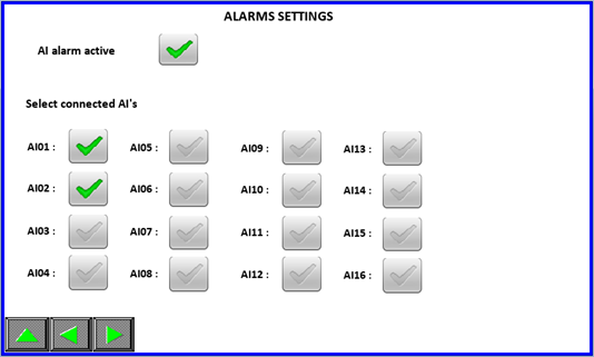
GENERAL SETTINGS
Here you can acess the HMI setting page and enable or disable the PM-8 functionality. Minimal critical pressure is used to automatically set PM-8 ENABLE/DISABLE button to off if pressure is under that value and all compressors are shutdown. Line voltage setting is used for power calculation ( see below). You can also choose energy specific display or power specific display.
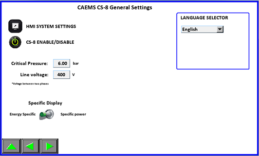
On this page users can select HMI display language by language selector
:
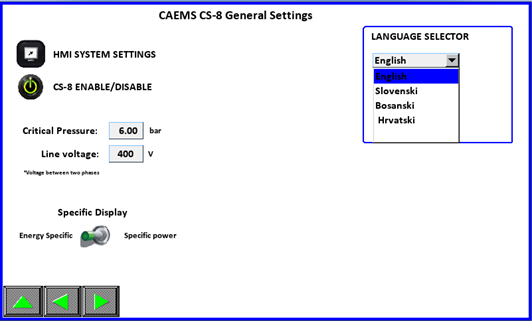
Depending on user location and expected language the selection can be
upgraded. After finishing the setting up of the input return to SETUP
page by pressing the button.
EMCS SETTINGS
If EMCS is purchased and enabled in login page you can acess EMCS
SETTINGS by pressing the EMCS SETTINGS button and a setup screen for
the control system will be displayed. Here you can input EMCS options
such as control pressure, timers and control mode.
 the pages with the navigation buttons as usual.
PRESSURE SETTINGS
On this page user setups EMCS pressure parameters.PRESSURE SETPIONT:
is the desired pressure of the systemCRITICAL PRESSURE: is the
minimum pressure of the system. If pressure goes below that point an
alarm will be issued and additional compressors will be
started.PRESSURE SETPOINT OFFSET: is the below and under Pressure
Setpoint setting. If pressure reaches (Pressure Setpoint + Pressure
Setpoint Offset) next compressor will be unloaded and if pressure
falls below (Pressure Setpoint - Pressure Setpoint Offset) next
compressor will be loaded.MAX. CRITICAL PRESSURE: If pressure
reaches this set value emergency stopping of compressors is
programmed.If pressure settings are setup as above the EMCS will try to
maintain a system pressure between 7,5 and 6,5 bar. If pressure goes
higher compressor will be unloaded, if pressure falls below next
compressor is loaded.
TIMERS
On this page user setups EMCS TIMER settings:NORMAL START: time that
EMCS will wait before starting another compressor in the system if
system pressure falls below (Pressure Setpoint - Pressure Setpoint
Offset).CRITICAL START: time that EMCS will wait before starting
another compressor if system pressure falls below critical pressure set
pointLoad/Unload: time that EMCS will wait before loading or
unloading next compressor.Unload Stop(long): time in which next
unloaded compressor will be stoppedUnload Stop(short): time in which
next unloaded compressor will be stoppedDifference between long/short
timer is in the number of unloaded compressor. If only two or less
compressors are unloaded than long timer is used, otherwise long timer
is used.
 IMPORTANT! PRIORITY MUST NOT BE SET AS ZERO. TWO COMPRESSOR CAN’T HAVE
SAME PRIORITY NUMBER!!!Compressor with the HIGHEST starting priority
number will be started FIRST, compressor with LOWEST starting priority
number will be started last.Compressor with the HIGHEST stopping
priority number will be stopped FIRST, compressor with LOWEST stopping
priority number will be stopped last.
IMPORTANT! PRIORITY MUST NOT BE SET AS ZERO. TWO COMPRESSOR CAN’T HAVE
SAME PRIORITY NUMBER!!!Compressor with the HIGHEST starting priority
number will be started FIRST, compressor with LOWEST starting priority
number will be started last.Compressor with the HIGHEST stopping
priority number will be stopped FIRST, compressor with LOWEST stopping
priority number will be stopped last.
CONTROL MODE
Here you select desire control mode. Only one mode can be selected. You
can adjust settings of control mode by clicking on specific icon. You
can click the icon before enabling specific control mode.
PRIORITIES
In this control mode you have two possible options. One option is to
adjust only Primary Starting Priorities and Primary Stopping
Priorities. You can also enable Switching Prio option and system
will then change the compressors priorites every defined days.The LED
shows us which priorities are used at the momentàPrimary or secondary.
ENERGY MODE SETTINGS
Input your flow values and priorities will be acceppted if system flow
is in determined range. Determine the flow average time calculation.
SCHEDULES
You can input three different schedules that must cover whole week. When
next schedule is started previous is aborted. When schedule is active
the correct priorities will be accepted.
Compressor System (CS) Stop-Start FUNCTION
On this page user can stop and start whole compressor system ( CS). By activating this function system will calculate how many compressors are needed to fill the system in prefill time specified by operator. So, when “Auto Start CS” button is pressed, system starts compressors ( how many is calculated from “Pressure tank capacity” and “Prefill time”). When pressing “Auto Stop CS” all compressors will be stopped and system will wait for next command to start CS.
If Start/Stop schedule is enabled, operator has option to adjust
schedule when CS will start and when stop. On picture below we see that
schedule for Monday is disabledàRed LED (If hour for start and stop is
24 then schedule for this day is disabled). For Tuesday we see that
schedule is enabledàGreen LED and time is set. Compressor station will
start at 5.30 and stop at 15.00.Here you can adjust schedule for each
day.
After finishing setup return to the SP page by pressing the UP button.
CFC SETTINGS
From the SETUP PAGE, if the option is purchased and enabled pressing the
button enters the CFC menu.Here is the main setting page for CALMS
Flowcontroller (CFC). Operation mode can be Manual or Auto. In Manual
mode we can manually open MRV1 valve from 0-100% in order to test its
functionality
In Auto mode we set the Setpoint value of Pressure that we want to
maintain after Flowcontroller. We have Default setpoint which is used if
there is no other CFC Function selected, otherwise other Setpoints are
used.Also for BRV1 valve we have Manual or Auto mode. In Manual mode we
can also manually open BRV1 valve from 0-100% in order to test its
functionality. In Auto mode we adjust the CFC Pressure Diference. If
pressure falls below Setpoint-CFC Press. Diference CFC opens in
order to raise outlet pressure.
With clicking on icon you are redirected to CFC status page, which is
described in upper pages.
System offers to set the Setpoint for CFC from two different functions.
If none function is selected Default Setpoint is used.
DI Setpoint Function
Here we can set Setpoint via three digital inputs which are predefined
(DI6, DI7, DI8). When certain DI is activated it turns green and at the
bottom on right side you can see which Setpoint is used at the moment.
Only one DI can be activated at once otherwise DI Setpoint Alarm is
triggered and Default Setpoint is used.
CFC Schedule Function
Here you can adjust schedule for CFC. For each day you can adjust two
different setpointsà SP1 and SP2. When specific Setpoint is used it
turns green. If time adjustments are not OK (if hour setting is 24, or
both SP of the same day have set same time) the setting for Setpoint
disappears and system will not use this SP.
IMOP
Pressing the button enters the IMOP menu. A readings reset button per
compressor is available. IMOP is a function that monitors and writes
values of all AIP variables (all voltages, all currents, all CosFi-s,
reactive power, real power,…) in CSV format and uploads it. If
compressor is ON/OFF type it writes and uploads both states in
difference from VSD compressors for which writes and uploads only one
state à RUNNING. By resetting IMOP readings will be performed and
uploaded again.
SHUTOFF VALVE SETTINGS
Pressing the button enters the SHUT OFF VALVES menu. If this option is
purchased, operator can set three different shut off valves. They can be
regulated manually ( open-close ) or automatically through schedule
setup. We also can set the name of each valve for easier
recognization.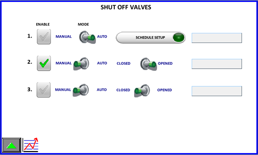
If we want to set the schedule, we click on and then adjust schedule
settings for specific Shut off valve. When is green it means that second
SOV is enabled, otherwise its regulation is disabled.
VOLTAGE IMBALANCE
Pressing the button enters the specific menu. Here you can view
function status, activate readings and reset all voltage imbalance
readings. Voltage imbalance is a function that uploads an alarm log file
when supply voltage varies for more than 3% from rated voltage. When
first event happens, a timer of 300 s starts and after the expiry
function waits for next voltage imbalance. After third event of
imbalance the function locks and waits for manual reset on HMI. If the
LOCKED icon is active a reading has already been uploaded. Press and
hold the reset button to reactivate reading and uploading data.
ANALISYS LOG FUNCTION
Pressing the button enters the LOG menu. When you activate this
function, system uploads all values of all variables from 1 minute
before and 1 minute after the function has been activated.

 WARNING: Risk of
Danger
WARNING: Risk of
Danger WARNING: Risk of Electric
Shock
WARNING: Risk of Electric
Shock WARNING: Consult
Manual
WARNING: Consult
Manual