
ABB Power Meter B23/B24
ABB Power Meter B23/B24 with CAL-EDGE device
The ABB power meter is connected to the CAL-EGDE device via Modbus RTU protocol. Please wire the power meter according to the device you have:
- CAL-EDGE-0 device:
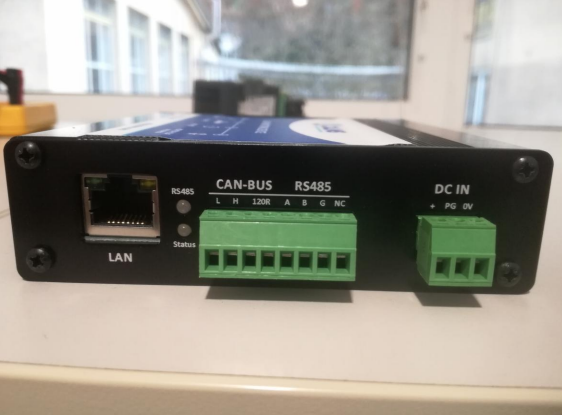
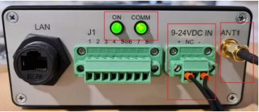
The device is powered with 24VDC. Connect the power supply to the labeled terminals (watch the polarity) on screw-type phoenix connector. On the photo below is the side view of the device and on the right is the connector for the power supply.
On the electrical schematic below is shown how you should connect the power supply. It is crucial to wire it correctly.
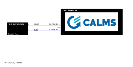
The ABB Power meter is powered directly from the voltages of your 3-phase system. When you connect L1,L2 and L3 (and N) the meter powers itself.
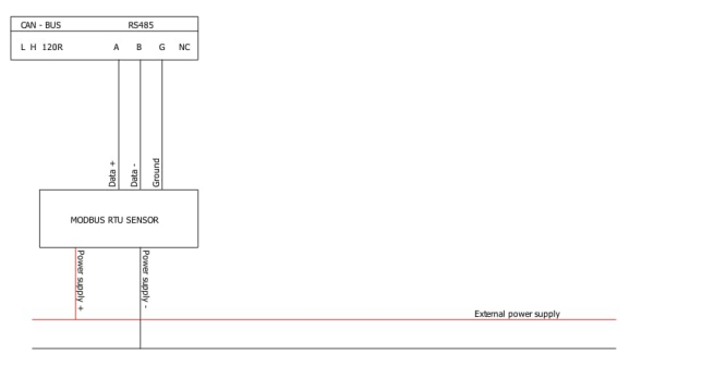
Next, to wire the devices for Modbus RTU communication you need to:
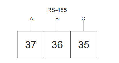
- Connect terminal labeled A on the CAL-EDGE-0 device with the terminal labeled 37 (or A) on the power meter.
- Connect terminal labeled B on the CAL-EDGE-0 device with the terminal labeled 36 (or B) on the power meter.
Below are the electrical schematics on how to correctly wire the devices:
- CAL-EDGE-8 device:
The device is powered with 24VDC. Connect the power supply to the labeled terminals (watch the polarity) on screw-type phoenix connector. On the photo below is the side view of the device and on the right is the connector for the power supply.
On the electrical schematic below is shown how you should connect the power supply. It is crucial to wire it correctly.
The ABB Power meter is powered directly from the voltages of your 3-phase system. When you connect L1,L2 and L3 (and N) the meter powers itself.
Next, to wire the devices for Modbus RTU communication you need to:
- Connect terminal labeled J1-1 on the CAL-EDGE-8 device with the terminal labeled 37 (or A) on the power meter.
- Connect terminal labeled J1-2 on the CAL-EDGE-8 device with the terminal labeled 36 (or B) on the power meter.
Below are the electrical schematics on how to correctly wire the devices:
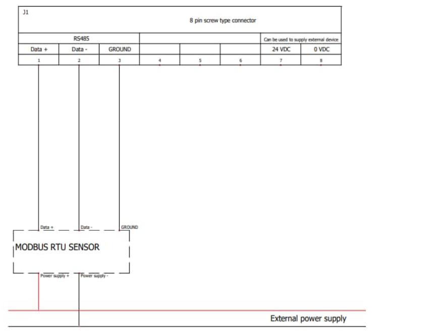
ABB Power Meter B23/B24 with CAL-PM-X device
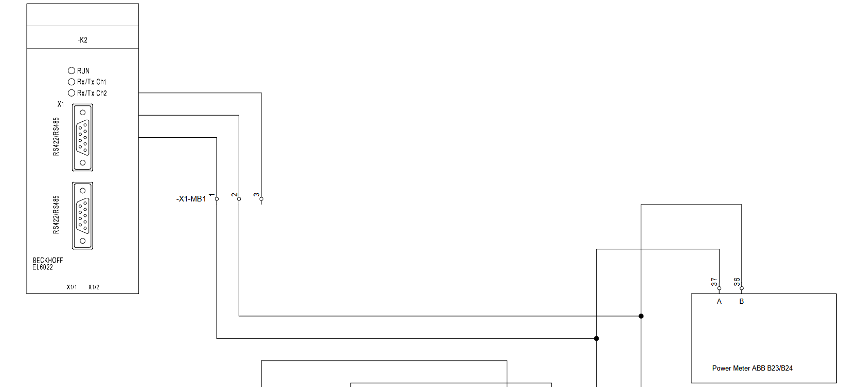
The ABB power meter is connected to the CAL-PM-X device via Modbus RTU protocol. The power meter is connected to the PLC in the CAL-PM device cabinet. For the Modbus RTU communication a terminal is added - EL6022.
The electrical schematic below shows how the power meter is wired to the CAL-PM device.
Acrel DTSD1352
Acrel DTSD1352 with CAL-EDGE device
The Acrel power meter is connected to the CAL-EGDE device via Modbus RTU protocol. Please wire the power meter according to the device you have:
- CAL-EDGE-0 device:
The device is powered with 24VDC. Connect the power supply to the labeled terminals (watch the polarity) on screw-type phoenix connector. On the photo below is the side view of the device and on the right is the connector for the power supply.
On the electrical schematic below is shown how you should connect the power supply. It is crucial to wire it correctly.
The Acrel power meter is powered directly from the voltages of your 3-phase system. When you connect L1,L2 and L3 (and N) the meter powers itself.
Next, to wire the devices for Modbus RTU communication you need to:
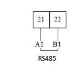
- Connect terminal labeled A on the CAL-EDGE-0 device with the terminal labeled 21 (or A1) on the power meter.
- Connect terminal labeled B on the CAL-EDGE-0 device with the terminal labeled 22 (or B1) on the power meter.
Below are the electrical schematics on how to correctly wire the devices:
- CAL-EDGE-8 device:
The device is powered with 24VDC. Connect the power supply to the labeled terminals (watch the polarity) on screw-type phoenix connector. On the photo below is the side view of the device and on the right is the connector for the power supply.
On the electrical schematic below is shown how you should connect the power supply. It is crucial to wire it correctly.
The Acrel power meter is powered directly from the voltages of your 3-phase system. When you connect L1,L2 and L3 (and N) the meter powers itself.
Next, to wire the devices for Modbus RTU communication you need to:
- Connect terminal labeled J1-1 on the CAL-EDGE-8 device with the terminal labeled 21 (or A1) on the power meter.
- Connect terminal labeled J1-2 on the CAL-EDGE-8 device with the terminal labeled 22 (or B1) on the power meter.
Below are the electrical schematics on how to correctly wire the devices:
CAA POM 100x01 (with display)
CAA POM 100x01 (with display) with CAL-EDGE device
The CAA power meter is connected to the CAL-EGDE device via Modbus RTU protocol. Please wire the power meter according to the device you have:
- CAL-EDGE-0 device:
The device is powered with 24VDC. Connect the power supply to the labeled terminals (watch the polarity) on screw-type phoenix connector. On the photo below is the side view of the device and on the right is the connector for the power supply.
On the electrical schematic below is shown how you should connect the power supply. It is crucial to wire it correctly.
The CAA power meter is powered with 24VDC. Please refer to the photo below on how to power the meter.
- Connect Power supply + to the L terminal on the meter.
- Connect Power supply - to the N terminal on the meter.

Next, to wire the devices for Modbus RTU communication you need to:
- Connect terminal labeled A on the CAL-EDGE-0 device with the terminal labeled A on the power meter.
- Connect terminal labeled A on the CAL-EDGE-0 device with the terminal labeled B on the power meter.
Below are the electrical schematics on how to correctly wire the devices:
- CAL-EDGE-8 device:
The device is powered with 24VDC. Connect the power supply to the labeled terminals (watch the polarity) on screw-type phoenix connector. On the photo below is the side view of the device and on the right is the connector for the power supply.
On the electrical schematic below is shown how you should connect the power supply. It is crucial to wire it correctly.
The CAA power meter is powered with 24VDC. Please refer to the photo below on how to power the meter.
- Connect Power supply + to the L terminal on the meter.
- Connect Power supply - to the N terminal on the meter.
Next, to wire the devices for Modbus RTU communication you need to:
- Connect terminal labeled J1-1 on the CAL-EDGE-8 device with the terminal labeled A on the power meter.
- Connect terminal labeled J1-2 on the CAL-EDGE-8 device with the terminal labeled B on the power meter.
Below are the electrical schematics on how to correctly wire the devices:
CAA Power meter - POM100 (no display)
CAA Power meter - POM100 (no display) with CAL-EDGE device
The CAA power meter is connected to the CAL-EGDE device via Modbus RTU protocol. Please wire the power meter according to the device you have:
- CAL-EDGE-0 device:
The device is powered with 24VDC. Connect the power supply to the labeled terminals (watch the polarity) on screw-type phoenix connector. On the photo below is the side view of the device and on the right is the connector for the power supply.
On the electrical schematic below is shown how you should connect the power supply. It is crucial to wire it correctly.
The CAA power meter is powered with 85-265V AC/DC or 24VDC. Please refer to the photo below on how to power the meter.
- Connect Power supply + to the V+ terminal on the meter.
- Connect Power supply - to the V- terminal on the meter.
Next, to wire the devices for Modbus RTU communication you need to:
- Connect terminal labeled A on the CAL-EDGE-0 device with the terminal labeled A on the power meter.
- Connect terminal labeled B on the CAL-EDGE-0 device with the terminal labeled B on the power meter.
Below are the electrical schematics on how to correctly wire the devices:
- CAL-EDGE-8 device:
The device is powered with 24VDC. Connect the power supply to the labeled terminals (watch the polarity) on screw-type phoenix connector. On the photo below is the side view of the device and on the right is the connector for the power supply.
On the electrical schematic below is shown how you should connect the power supply. It is crucial to wire it correctly.
The CAA power meter is powered with 85-265V AC/DC or 24VDC. Please refer to the photo below on how to power the meter.
- Connect Power supply + to the V+ terminal on the meter.
- Connect Power supply - to the V- terminal on the meter.
Next, to wire the devices for Modbus RTU communication you need to:
- Connect terminal labeled J1-1 on the CAL-EDGE-8 device with the terminal labeled A on the power meter.
- Connect terminal labeled J1-2 on the CAL-EDGE-8 device with the terminal labeled B on the power meter.
Below are the electrical schematics on how to correctly wire the devices:
DUCATI Energia DE-RW
DUCATI Energia DE-RW with CAL-EDGE device
The DUCATI power meter is connected to the CAL-EGDE device via Modbus TCP protocol. Please wire the power meter according to the device you have:
- CAL-EDGE-0 device:
The device is powered with 24VDC. Connect the power supply to the labeled terminals (watch the polarity) on screw-type phoenix connector. On the photo below is the side view of the device and on the right is the connector for the power supply.
On the electrical schematic below is shown how you should connect the power supply. It is crucial to wire it correctly.
- CAL-EDGE-8 device:
The device is powered with 24VDC. Connect the power supply to the labeled terminals (watch the polarity) on screw-type phoenix connector. On the photo below is the side view of the device and on the right is the connector for the power supply.
On the electrical schematic below is shown how you should connect the power supply. It is crucial to wire it correctly.
Energeia energy meter
Energeia energy meter with CAL-EDGE device
The Energeia power meter is connected to the CAL-EGDE device via Modbus RTU protocol. Please wire the power meter according to the device you have:
- CAL-EDGE-0 device:
The device is powered with 24VDC. Connect the power supply to the labeled terminals (watch the polarity) on screw-type phoenix connector. On the photo below is the side view of the device and on the right is the connector for the power supply.
On the electrical schematic below is shown how you should connect the power supply. It is crucial to wire it correctly.
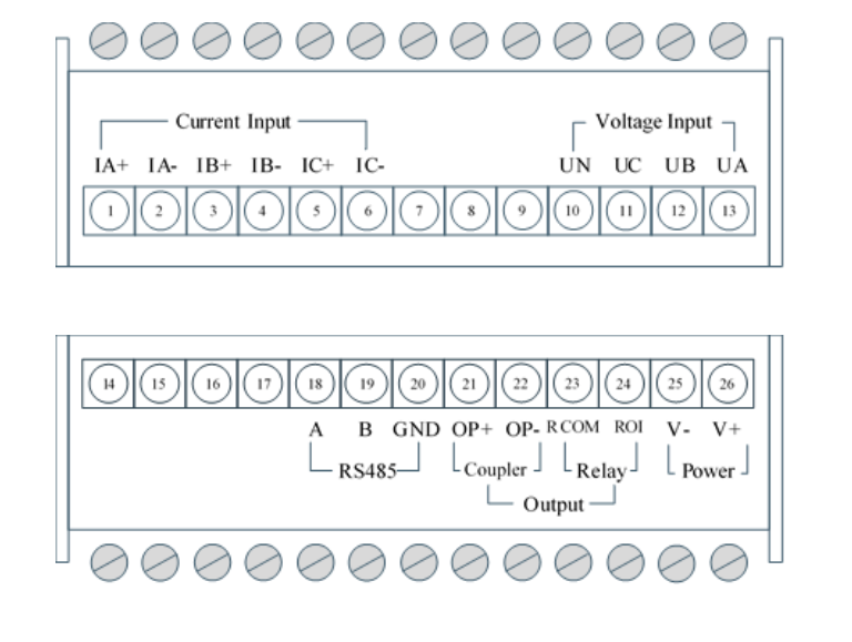
The Energeia power meter is powered with 95-265V AC or 110-260V DC . Please refer to the photo below on how to power the meter.
- Connect Power supply + to the L terminal on the meter.
- Connect Power supply - to the N terminal on the meter.
Next, to wire the devices for Modbus RTU communication you need to:
- Connect terminal labeled A on the CAL-EDGE-0 device with the terminal labeled A (12) on the power meter.
- Connect terminal labeled B on the CAL-EDGE-0 device with the terminal labeled B (11) on the power meter.
Below are the electrical schematics on how to correctly wire the devices:
- CAL-EDGE-8 device:
The device is powered with 24VDC. Connect the power supply to the labeled terminals (watch the polarity) on screw-type phoenix connector. On the photo below is the side view of the device and on the right is the connector for the power supply.
On the electrical schematic below is shown how you should connect the power supply. It is crucial to wire it correctly.
The Energeia power meter is powered with 95-265V AC or 110-260V DC . Please refer to the photo below on how to power the meter.
- Connect Power supply + to the L terminal on the meter.
- Connect Power supply - to the N terminal on the meter.
Next, to wire the devices for Modbus RTU communication you need to:
- Connect terminal labeled J1-1 on the CAL-EDGE-8 device with the terminal labeled A (12) on the power meter.
- Connect terminal labeled J1-2 on the CAL-EDGE-8 device with the terminal labeled B (11) on the power meter.
Below are the electrical schematics on how to correctly wire the devices:
VP Instruments Janitza UMG96RM
VP Instruments Janitza UMG96RM with CAL-EDGE device
The Janitza power meter is connected to the CAL-EGDE device via Modbus RTU protocol. Please wire the power meter according to the device you have:
- CAL-EDGE-0 device:
The device is powered with 24VDC. Connect the power supply to the labeled terminals (watch the polarity) on screw-type phoenix connector. On the photo below is the side view of the device and on the right is the connector for the power supply.
On the electrical schematic below is shown how you should connect the power supply. It is crucial to wire it correctly.
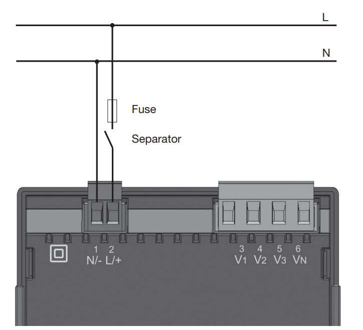
The Janitza power meter is with 20-250V AC or 20-300V DC. Please refer to the photo below on how to power the meter.
- Connect Power supply + to the L/+ terminal on the meter.
- Connect Power supply - to the N/- terminal on the meter.
NOTE: The supply voltage must be connected via a UL/IEC approved fuse (6A, type C)
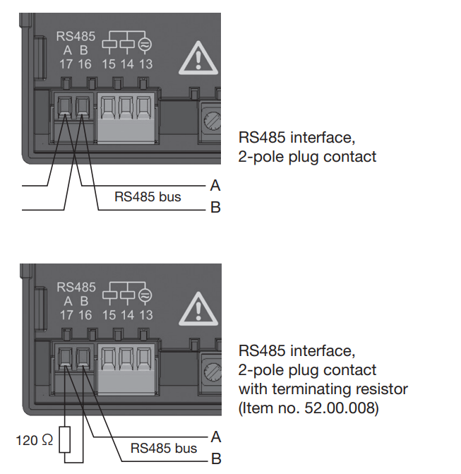
Next, to wire the devices for Modbus RTU communication you need to:
- Connect terminal labeled A on the CAL-EDGE-0 device with the terminal labeled A (17) on the power meter.
- Connect terminal labeled B on the CAL-EDGE-0 device with the terminal labeled B (16) on the power meter.
Below are the electrical schematics on how to correctly wire the devices:
- CAL-EDGE-8 device:
The device is powered with 24VDC. Connect the power supply to the labeled terminals (watch the polarity) on screw-type phoenix connector. On the photo below is the side view of the device and on the right is the connector for the power supply.
On the electrical schematic below is shown how you should connect the power supply. It is crucial to wire it correctly.
The Janitza power meter is with 20-250V AC or 20-300V DC. Please refer to the photo below on how to power the meter.
- Connect Power supply + to the L/+ terminal on the meter.
- Connect Power supply - to the N/- terminal on the meter.
NOTE: The supply voltage must be connected via a UL/IEC approved fuse (6A, type C)
Next, to wire the devices for Modbus RTU communication you need to:
- Connect terminal labeled J1-1 on the CAL-EDGE-8 device with the terminal labeled A (17) on the power meter.
- Connect terminal labeled J1-2 on the CAL-EDGE-8 device with the terminal labeled B (16) on the power meter.
Below are the electrical schematics on how to correctly wire the devices:
VP Instruments 3-Phase Power Meter
VP Instruments 3-Phase Power Meter with CAL-EDGE device
The VP Instruments power meter is connected to the CAL-EGDE device via Modbus RTU protocol. Please wire the power meter according to the device you have:
- CAL-EDGE-0 device:
The device is powered with 24VDC. Connect the power supply to the labeled terminals (watch the polarity) on screw-type phoenix connector. On the photo below is the side view of the device and on the right is the connector for the power supply.
On the electrical schematic below is shown how you should connect the power supply. It is crucial to wire it correctly.
The VP Instruments power meter is powered from the measured voltage.
Next, to wire the devices for the Modbus RTU communication you need to:
- Connect terminal labeled A on the CAL-EDGE-0 device with the terminal labeled A on the power meter.
- Connect terminal labeled B on the CAL-EDGE-0 device with the terminal labeled B on the power meter.
Below are the electrical schematics on how to correctly wire the devices:

-CAL-EDGE-8 device:
The device is powered with 24VDC. Connect the power supply to the labeled terminals (watch the polarity) on screw-type phoenix connector. On the photo below is the side view of the device and on the right is the connector for the power supply.
On the electrical schematic below is shown how you should connect the power supply. It is crucial to wire it correctly.
The VP Instruments power meter is powered from the measured voltage.
Next, to wire the devices for the Modbus RTU communication you need to:
- Connect terminal labeled J1-1 on the CAL-EDGE-8 device with the terminal labeled A on the power meter.
- Connect terminal labeled J1-2 on the CAL-EDGE-8 device with the terminal labeled B on the power meter.
Below are the electrical schematics on how to correctly wire the devices:
Secure Elite 443 Power meter
Secure Elite 443 Power meter with CAL-EDGE devices
-CAL-EDGE-0 device:
The device is powered with 24VDC. Connect the power supply to the labeled terminals (watch the polarity) on screw-type phoenix connector. On the photo below is the side view of the device and on the right is the connector for the power supply.
On the electrical schematic below is shown how you should connect the power supply. It is crucial to wire it correctly.
The Secure Elite 443 Power meter is powered with 80-300 V AC/DC or 24-60 V DC. Please refer to the photo below on how to power the meter.
- Connect Power supply + to the +/P terminal on the meter.
- Connect Power supply - to the -/N terminal on the meter.
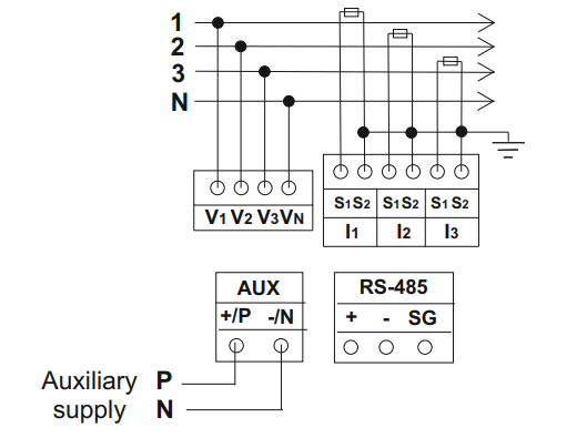
Next, to wire the devices for the Modbus RTU communication you need to:
- Connect terminal labeled A on the CAL-EDGE-0 device with the terminal labeled + (RS-485) on the power meter.
- Connect terminal labeled B on the CAL-EDGE-0 device with the terminal labeled - (RS-485) on the power meter.
Below are the electrical schematics on how to correctly wire the devices:
-CAL-EDGE-8 device:
The device is powered with 24VDC. Connect the power supply to the labeled terminals (watch the polarity) on screw-type phoenix connector. On the photo below is the side view of the device and on the right is the connector for the power supply.
On the electrical schematic below is shown how you should connect the power supply. It is crucial to wire it correctly.
The Secure Elite 443 Power meter is powered with 80-300 V AC/DC or 24-60 V DC. Please refer to the photo below on how to power the meter.
- Connect Power supply + to the +/P terminal on the meter.
- Connect Power supply - to the -/N terminal on the meter.
Next, to wire the devices for the Modbus RTU communication you need to:
- Connect terminal labeled J1-1 on the CAL-EDGE-8 device with the terminal labeled + (RS-485) on the power meter.
- Connect terminal labeled J1-2 on the CAL-EDGE-8 device with the terminal labeled - (RS-485) on the power meter.
Below are the electrical schematics on how to correctly wire the devices:
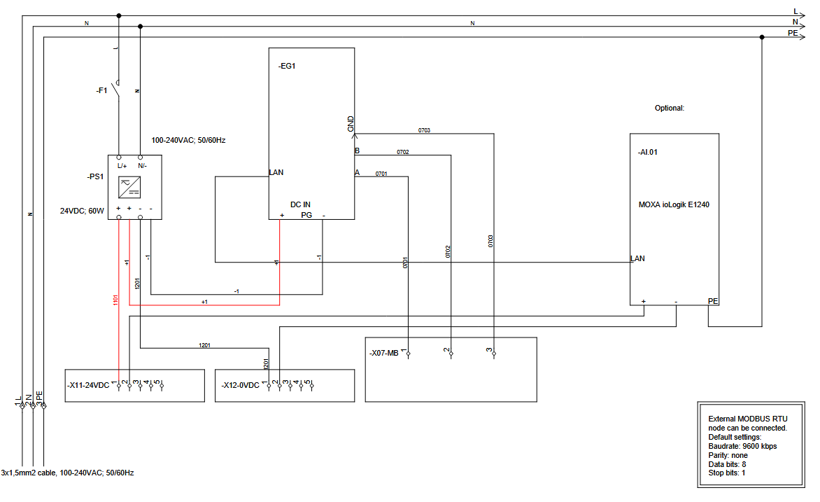
Secure Elite 443 Power meter with CAL-EDGE-PM device:
The device is powered with 100-240VAC. Connect the power supply to the labeled terminals L, N and ground.
On the electrical schematic below is shown how you should connect the power supply. It is crucial to wire it correctly.
The Secure Elite 443 Power meter is powered with 80-300 V AC/DC or 24-60 V DC. Please refer to the photo below on how to power the meter.
Connect Power supply + to the +/P terminal on the meter.
Connect Power supply - to the -/N terminal on the meter.
Next, to wire the devices for the Modbus RTU communication you need to:
- Connect terminal labeled 1 (on the X07 MB terminal block) on the CAL-EDGE-PM device with the terminal labeled + (RS-485) on the power meter.
- Connect terminal labeled 2 (on the X07 MB terminal block) on the CAL-EDGE-PM device with the terminal labeled - (RS-485) on the power meter.
Below are the electrical schematics on how to correctly wire the devices:
Secure 300 Power meter
Secure 300 Power meter with the CAL-EDGE devices:
-CAL-EDGE-0 device:
The device is powered with 24VDC. Connect the power supply to the labeled terminals (watch the polarity) on screw-type phoenix connector. On the photo below is the side view of the device and on the right is the connector for the power supply.
On the electrical schematic below is shown how you should connect the power supply. It is crucial to wire it correctly.
The Secure 300 Power meter is powered with 40-300V AC (50/60Hz) / DC. Please refer to the photo below on how to power the meter.
- Connect Power supply + to the +/P terminal on the meter.
- Connect Power supply - to the -/N terminal on the meter.
Next, to wire the devices for Modbus RTU communication you need to:
- Connect terminal labeled A on the CAL-EDGE-0 device with the terminal labeled
Rayleigh Instruments RI-D440
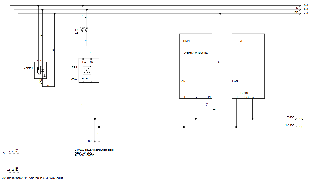
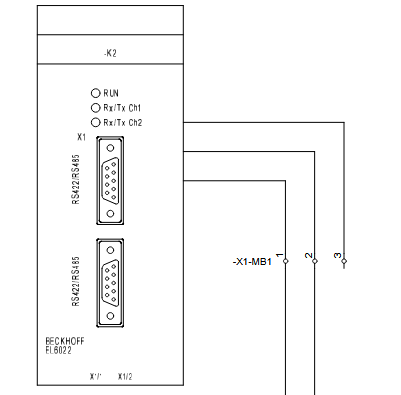
Rayleigh Instruments RI-D440 with CAL-PM-X device:
The CAL-PM-X device is powered with 110VAC (60Hz) / 230VAC (50Hz). On the electrical schematic below is shown how you should connect the power supply. It is crucial to wire it correctly.
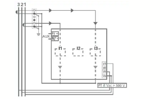
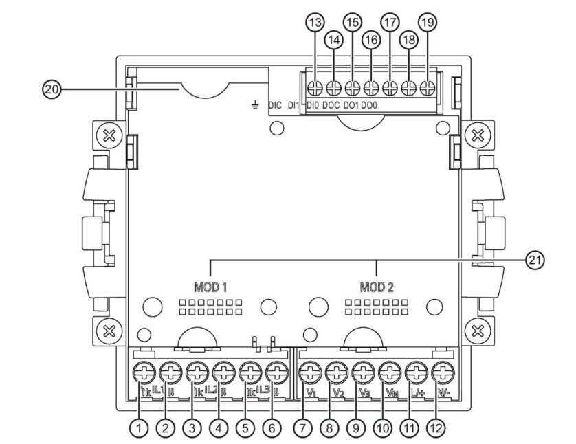
The Rayleigh RI-D440 Power meter is powered from the measured voltage. Please refer to the photo below on how to power the meter.
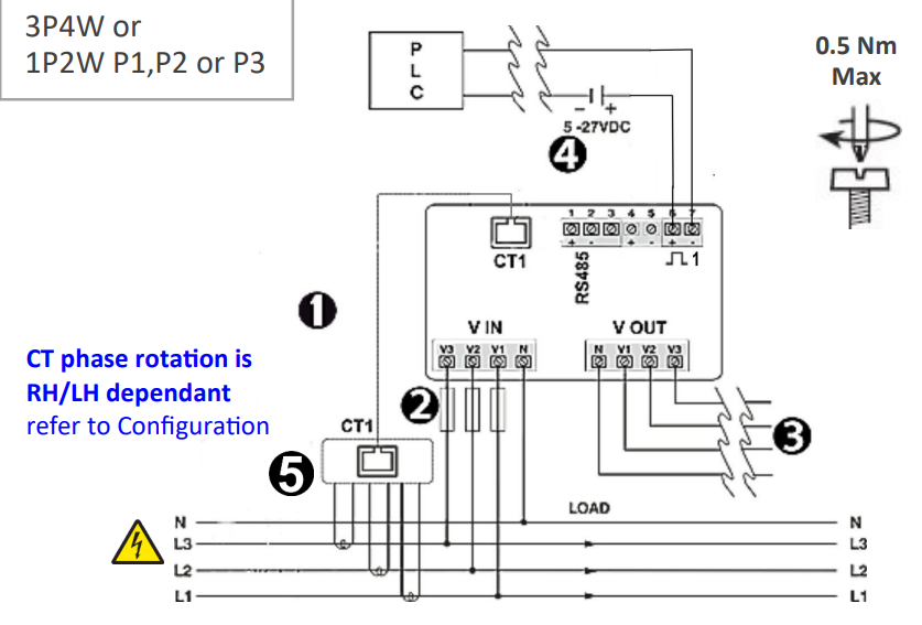
Next, to wire the devices for Modbus RTU communication you need to:
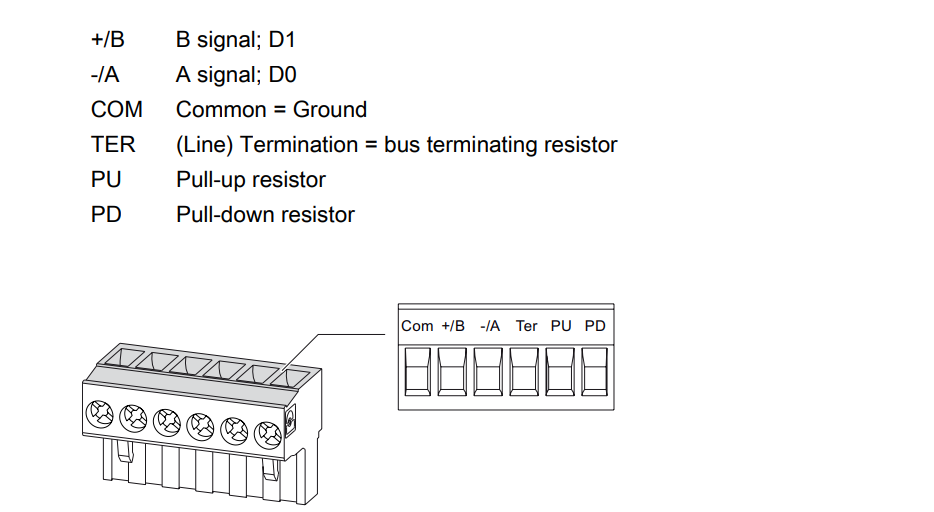
- Connect terminal labeled 1 (on the terminal block X-MB1) to the terminal labeled + (RS-485) on the power meter.
- Connect terminal labeled 2 (on the terminal block X-MB1) to the terminal labeled - (RS-485) on the power meter.
Below are the electrical schematics on how to correctly wire the devices:
Power monitoring device:
Siemens Sentron PAC 4200
Siemens Sentron PAC 4200 with CAL-EDGE devices:
-CAL-EDGE-0 device:
The device is powered with 24VDC. Connect the power supply to the labeled terminals (watch the polarity) on screw-type phoenix connector. On the photo below is the side view of the device and on the right is the connector for the power supply.
On the electrical schematic below is shown how you should connect the power supply. It is crucial to wire it correctly.
The Siemens Sentron PAC 4200 power monitoring device is powered with 95-240VAC / 110-340VDC. Please refer to the photo below on how to power the meter.
- Connect Power supply + to the L/+ terminal on the meter.
- Connect Power supply - to the N/- terminal on the meter.
Next, to wire the devices for Modbus RTU communication an expansion module for RS485 communication needs to be installed. The wiring is as follows:
- Connect terminal labeled A on the CAL-EDGE-0 device with the terminal labeled -/A on the expansion module.
- Connect terminal labeled B on the CAL-EDGE-0 device with the terminal labeled +/B on the expansion module.
Siemens Sentron PAC 3200
Siemens SENTRON 1020
Siemens Sentron PAC 3100
Siemens Sentron PAC 3220