
BEKO Dew point meter METPOINT DPM SD23
CAA Dew Point Sensor - Q Series
Dew Point Sensor - Q Series with CAL-PM-X device
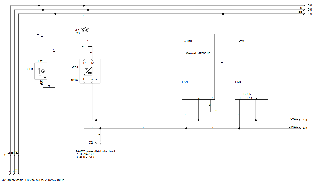
The CAL-PM-X device is powered with 110VAC (60Hz) / 230VAC (50Hz). On the electrical schematic below is shown how you should connect the power supply. It is crucial to wire it correctly.
The Dew Point sensor is powered with 24VDC. Please refer to the photo below on how to power the meter.
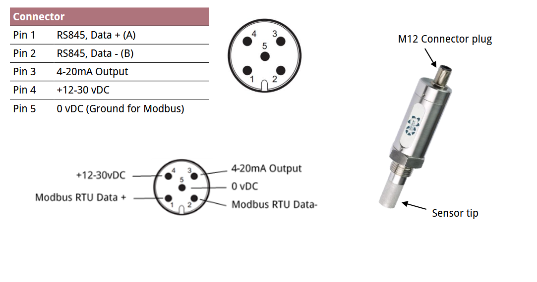
- Connect Pin4 (+12-30VDC) to a + terminal on the terminal block labeled 24VDC in the CAL-PM-X device.
- Connect Pin5 (0VDC) to a - terminal on the terminal block labeled 0VDC in the CAL-PM-X device.
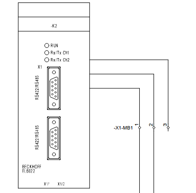
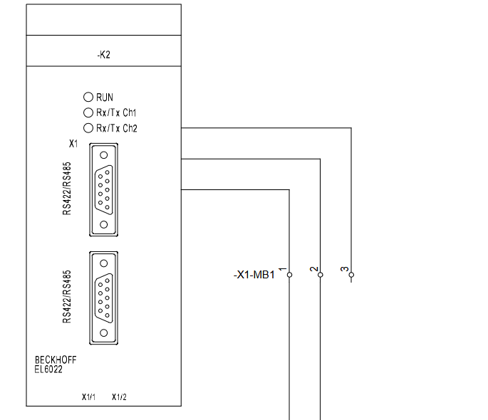
The Dew Point sensor is connected to the CAL-PM-X device via Modbus RTU protocol. The dew point sensor is connected to the PLC in the CAL-PM device cabinet. For the Modbus RTU communication a terminal is added - EL6022. To wire the sensor in the CAL-PM-X device you need to:
- Connect Pin1 (RS585 A) on the Dew Point sensor to the terminal labeled 1 (on the terminal block X1-MB1) on the CAL-PM-X device.
- Connect Pin2 (RS485 B) on the Dew Point sensor to the terminal labeled 2 (on the terminal block X1-MB1) on the CAL-PM-X device.
Below are the electrical schematics on how to correctly wire the devices:
Dew Point Sensor - Q Series with CAL-EDGE device
-CAL-EDGE-0 device:
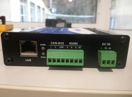
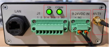
The device is powered with 24VDC. Connect the power supply to the labeled terminals (watch the polarity) on screw-type phoenix connector. On the photo below is the side view of the device and on the right is the connector for the power supply.
On the electrical schematic below is shown how you should connect the power supply. It is crucial to wire it correctly.
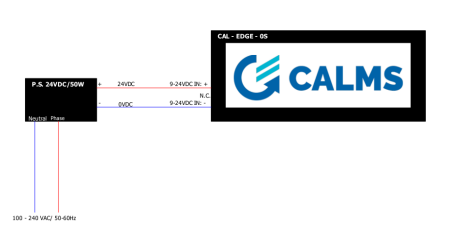
The Dew Point sensor is powered with 12-30VDC. Please refer to the photo below on how to power the sensor.
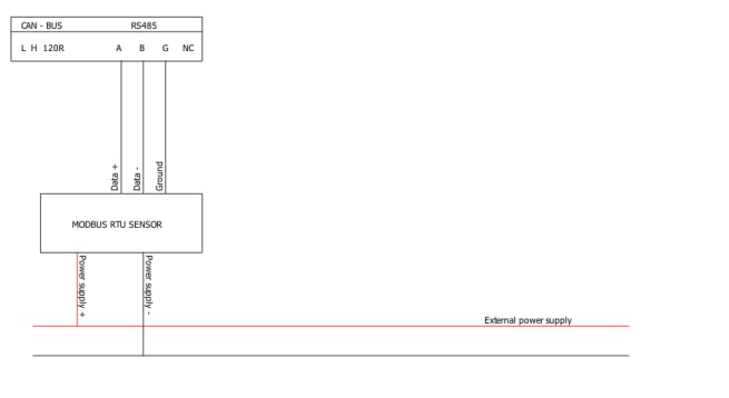
Next, to wire the devices for Modbus RTU communication you need to:
- Connect terminal labeled A on the CAL-EDGE-0 device with the Pin1 (RS485 A) on the dew point sensor.
- Connect terminal labeled B on the CAL-EDGE-0 device with the Pin2 (RS485 B) on the dew point sensor.
Below are the electrical schematics on how to correctly wire the devices:
-CAL-EDGE-8 device:
CAA Dew Point Sensor - A Series
CAA Dew Point Sensor - Mini Series
CAA Dew Point Sensor - Mini Series with CALMS CAL-PM-X device
The CAL-PM-X device is powered with 110VAC (60Hz) / 230VAC (50Hz). On the electrical schematic below is shown how you should connect the power supply. It is crucial to wire it correctly.
The Dew Point Mini sensor is powered with 24VDC. Please refer to the photo below on how to power the meter.
- Connect Pin4 (+12-30VDC) to a + terminal on the terminal block labeled 24VDC in the CAL-PM-X device.
- Connect Pin5 (0VDC) to a - terminal on the terminal block labeled 0VDC in the CAL-PM-X device.
The Dew Point Mini sensor is connected to the CAL-PM-X device via Modbus RTU protocol. The dew point sensor is connected to the PLC in the CAL-PM device cabinet. For the Modbus RTU communication a terminal is added - EL6022. To wire the sensor in the CAL-PM-X device you need to:
- Connect Pin1 (RS585 A) on the Dew Point sensor to the terminal labeled 1 (on the terminal block X1-MB1) on the CAL-PM-X device.
- Connect Pin2 (RS485 B) on the Dew Point sensor to the terminal labeled 2 (on the terminal block X1-MB1) on the CAL-PM-X device.
Below are the electrical schematics on how to correctly wire the devices:
CAA Dew Point Sensor - Mini Series with the CAL-EDGE devices
The Dew Point Sensor is connected to the CAL-EGDE device via Modbus RTU protocol. Please wire the power meter according to the device you have:
-CAL-EDGE-0 device:
The device is powered with 24VDC. Connect the power supply to the labeled terminals (watch the polarity) on screw-type phoenix connector. On the photo below is the side view of the device and on the right is the connector for the power supply.
On the electrical schematic below is shown how you should connect the power supply. It is crucial to wire it correctly.
The Dew Point sensor is powered with 12-30VDC. Please refer to the photo below on how to power the sensor.
Next, to wire the devices for Modbus RTU communication you need to:
- Connect terminal labeled A on the CAL-EDGE-0 device with the Pin1 (RS485 A) on the dew point sensor.
- Connect terminal labeled B on the CAL-EDGE-0 device with the Pin2 (RS485 B) on the dew point sensor.
Below are the electrical schematics on how to correctly wire the devices:
-CAL-EDGE-8 device:
The device is powered with 24VDC. Connect the power supply to the labeled terminals (watch the polarity) on screw-type phoenix connector. On the photo below is the side view of the device and on the right is the connector for the power supply.
On the electrical schematic below is shown how you should connect the power supply. It is crucial to wire it correctly.
The Dew Point sensor is powered with 12-30VDC. Please refer to the photo below on how to power the sensor.
- Connect terminal labeled J1-7 on the CAL-EDGE-8 device with the Pin4 (+12-30VDC) on the dew point sensor.
- Connect terminal labeled J1-8 on the CAL-EDGE-8 device with the Pin5 (0VDC) on the dew point sensor.
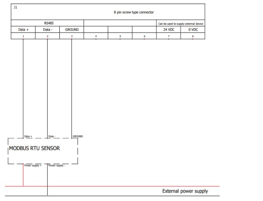
Next, to wire the devices for Modbus RTU communication you need to:
- Connect terminal labeled J1-1 on the CAL-EDGE-8 device with the Pin1 (RS485 A) on the dew point sensor.
- Connect terminal labeled J1-2 on the CAL-EDGE-8 device with the Pin2 (RS485 B) on the dew point sensor.
Below are the electrical schematics on how to correctly wire the devices:
CAA Dew Point Sensor - Mini Series with the CAL-EDGE-PM device
The device is powered with 110VAC, 60Hz or 230VAC,50Hz . Connect the power supply to the labeled terminals L, N and PE, below on the photo is shown how to power the device:
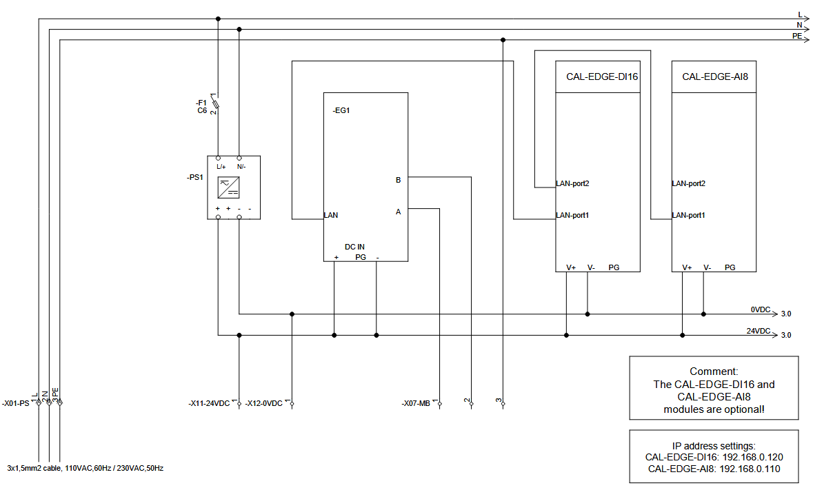
The Dew Point sensor is powered with 12-30VDC. Please refer to the photo below on how to power the sensor.
- Connect terminal on the terminal block labeled X11-24VDC on the CAL-EDGE-PM device with the Pin4 (+12-30VDC) on the dew point sensor.
- Connect terminal on the terminal block labeled X12-0VDC on the CAL-EDGE-PM device with the Pin5 (0VDC) on the dew point sensor.
Next, to wire the devices for Modbus RTU communication you need to:
- Connect terminal labeled 1 (on the terminal block X07-MB) on the CAL-EDGE-PM device with the Pin1 (RS485 A) on the dew point sensor.
- Connect terminal labeled 2 (on the terminal block X07-MB) on the CAL-EDGE-PM device with the Pin2 (RS485 B) on the dew point sensor.
Below are the electrical schematics on how to correctly wire the devices:
CAA Dew Point Sensor - Mini Series to the CAL-EDGE-8 device as an analog sensor
The device is powered with 24VDC. Connect the power supply to the labeled terminals (watch the polarity) on screw-type phoenix connector. On the photo below is the side view of the device and on the right is the connector for the power supply.
On the electrical schematic below is shown how you should connect the power supply. It is crucial to wire it correctly.
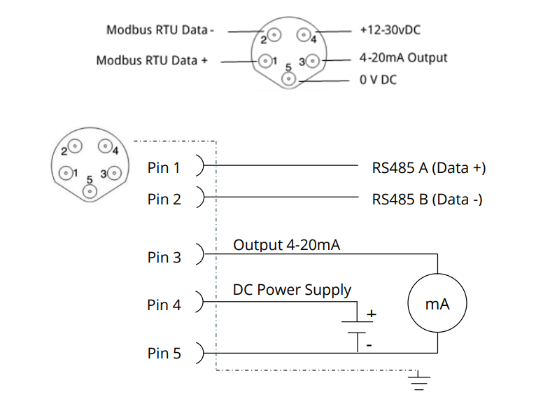
Open-end cable is used to connect custom 4-20mA sensors to the CAL-EDGE-8 device. When using open-end cable to connect a custom sensor, double check the connection.
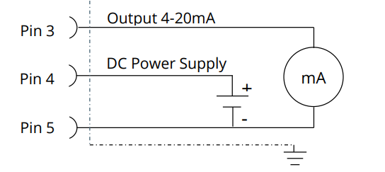
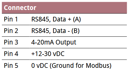
The data cable will be coloured coded as shown in the table below. It’s good practice to check the cable colours and make sure they match the chart below.
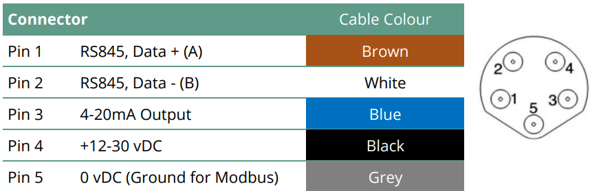
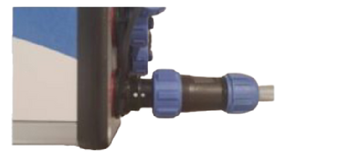
To connect the sensor to the CAL-EDGE-8 device, connect the connector to an analog input (AI1-AI8). Make sure that the white dot on the connector is aligned with white dot on the input on the device.Then tighten the cable with the nut.
CAA Dew Point Sensor - K Series
CAA Dew Point Sensor - K Series with CAL-EDGE devices
-CAL-EDGE-0 device:
The device is powered with 24VDC. Connect the power supply to the labeled terminals (watch the polarity) on screw-type phoenix connector. On the photo below is the side view of the device and on the right is the connector for the power supply.
On the electrical schematic below is shown how you should connect the power supply. It is crucial to wire it correctly.
The Dew Point sensor is powered with 12-30VDC. Please refer to the photo below on how to power the sensor.
Next, to wire the devices for Modbus RTU communication you need to:
- Connect terminal labeled A on the CAL-EDGE-0 device with the Pin1 (RS485 A) on the dew point sensor.
- Connect terminal labeled B on the CAL-EDGE-0 device with the Pin2 (RS485 B) on the dew point sensor.
Below are the electrical schematics on how to correctly wire the devices:
-CAL-EDGE-8 device:
The device is powered with 24VDC. Connect the power supply to the labeled terminals (watch the polarity) on screw-type phoenix connector. On the photo below is the side view of the device and on the right is the connector for the power supply.
On the electrical schematic below is shown how you should connect the power supply. It is crucial to wire it correctly.
The Dew Point sensor is powered with 12-30VDC. Please refer to the photo below on how to power the sensor.
- Connect terminal labeled J1-7 on the CAL-EDGE-8 device with the Pin4 (+12-30VDC) on the dew point sensor.
- Connect terminal labeled J1-8 on the CAL-EDGE-8 device with the Pin5 (0VDC) on the dew point sensor.
Next, to wire the devices for Modbus RTU communication you need to:
- Connect terminal labeled J1-1 on the CAL-EDGE-8 device with the Pin1 (RS485 A) on the dew point sensor.
- Connect terminal labeled J1-2 on the CAL-EDGE-8 device with the Pin2 (RS485 B) on the dew point sensor.
Below are the electrical schematics on how to correctly wire the devices:
Dew Point Sensor - K Series with the CAL-PM-X device
The CAL-PM-X device is powered with 110VAC (60Hz) / 230VAC (50Hz). On the electrical schematic below is shown how you should connect the power supply. It is crucial to wire it correctly.
The Dew Point sensor is powered with 12-30VDC. Please refer to the photo below on how to power the meter.
- Connect Pin4 (+12-30VDC) to a + terminal on the terminal block labeled 24VDC in the CAL-PM-X device.
- Connect Pin5 (0VDC) to a - terminal on the terminal block labeled 0VDC in the CAL-PM-X device.
The Dew Point sensor is connected to the CAL-PM-X device via Modbus RTU protocol. The dew point sensor is connected to the PLC in the CAL-PM device cabinet. For the Modbus RTU communication a terminal is added - EL6022. To wire the sensor in the CAL-PM-X device you need to:
- Connect Pin1 (RS585 A) on the Dew Point sensor to the terminal labeled 1 (on the terminal block X1-MB1) on the CAL-PM-X device.
- Connect Pin2 (RS485 B) on the Dew Point sensor to the terminal labeled 2 (on the terminal block X1-MB1) on the CAL-PM-X device.
Below are the electrical schematics on how to correctly wire the devices:
CS Instruments Dew Point sensor - FA510
Michel EasyDew dewpointmeter
PST Dewpoint Transmitter
SUTO S215